Arduino Clock with DS1307 Real-Time Module and 16×2 LCD
Step-by-Step Assembly and Configuration
Many Arduino clock projects available online use an I²C adapter for the LCD display to reduce the number of wires. While convenient, this approach introduces an additional board and another intermediate component into the design.
In this project, the LCD is connected directly in 4-bit mode — without additional drivers. The fewer intermediate components used in a device, the simpler the construction and the higher its reliability.
Technically, a clock can be implemented without a separate time module — Arduino is capable of counting seconds in software. However, once power is disconnected, the time would be lost.
For this reason, a Real-Time Clock (RTC) module — the DS1307 — is used. It stores the date and time independently of Arduino thanks to its built-in backup battery.
The result is a fully autonomous time display device that:
- shows the current time,
- shows the current date,
- preserves time settings after power loss,
- allows date and time configuration via computer.
Required Components
To build the project, you will need:
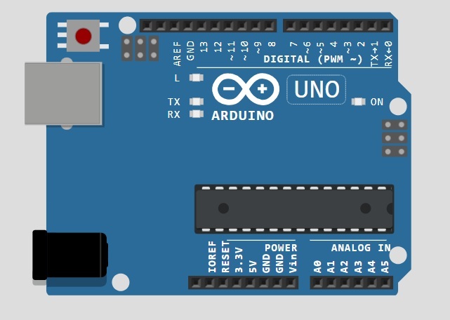
- Arduino Uno (or compatible board),
- DS1307 RTC module,
- 16×2 LCD display,
- Breadboard,
- Jumper wires,
- 10 kΩ potentiometer (for contrast adjustment),
- 1–2 kΩ resistor (for LCD backlight),
- USB cable.
The DS1307 module includes a battery that keeps the time even when Arduino is powered off.
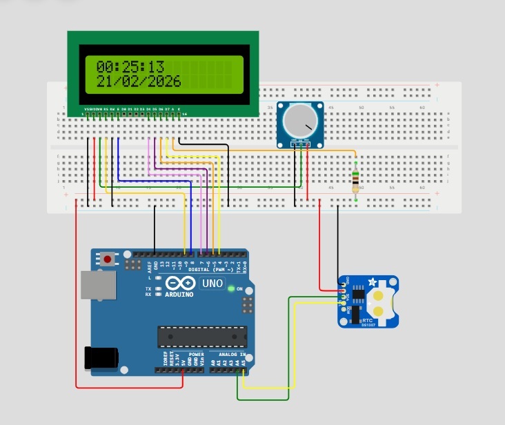
Connecting the Components
Before applying power, carefully verify all connections according to the wiring and schematic diagrams.
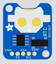
1. Connecting the DS1307 Module
The module is connected via the I²C bus:
- SDA → A4
- SCL → A5
- VCC → 5V
- GND → GND
Make sure that power and ground are connected correctly, as incorrect wiring may cause unstable module operation.
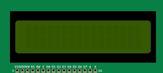
2. Connecting the 16×2 LCD
The display operates in 4-bit mode.
Signal connections:
- RS → 9
- E → 8
- D4 → 7
- D5 → 6
- D6 → 5
- D7 → 4
Contrast adjustment:
- Potentiometer outer pins → 5V and GND
- Potentiometer middle pin → VO (LCD contrast input)
Adjust the contrast so that characters are clearly visible without darkening the background excessively.
🔧 LCD Backlight Resistor
The 16×2 LCD includes an LED backlight.
Most displays require a current-limiting resistor.
In this build, a 2 kΩ resistor is used.
Connection:
- A (LED+) → through 2 kΩ resistor → 5V
- K (LED−) → GND
The resistor limits current through the LED backlight and prevents overheating.
Some LCD modules include an internal resistor, but universal displays may not. Using an external resistor ensures safe operation.
It is recommended to distribute power carefully across the breadboard rails and keep signal wires as short as possible. This reduces interference and improves stability.
Below is the schematic diagram of the device, which can be used to verify all connections before the first power-up.
Connecting to the Computer
Connect the Arduino board to your computer using a USB cable.
After connecting:
- Open Arduino IDE.
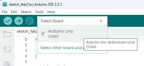
- Select:
- Tools → Board → Arduino Uno
- Tools → Port → appropriate COM port
Creating a New Sketch
Select:
File → New Sketch
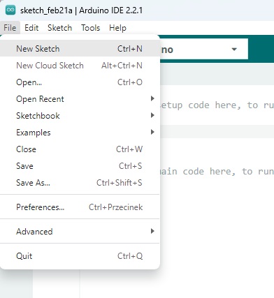
A new empty window will open.
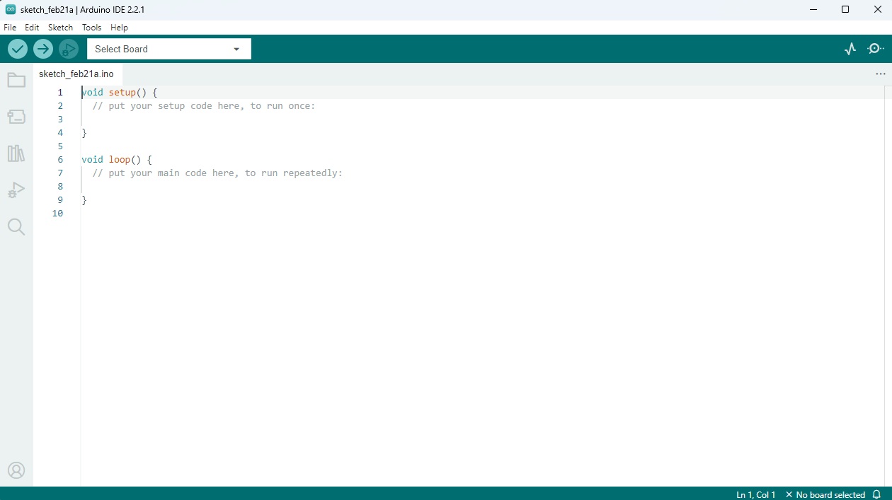
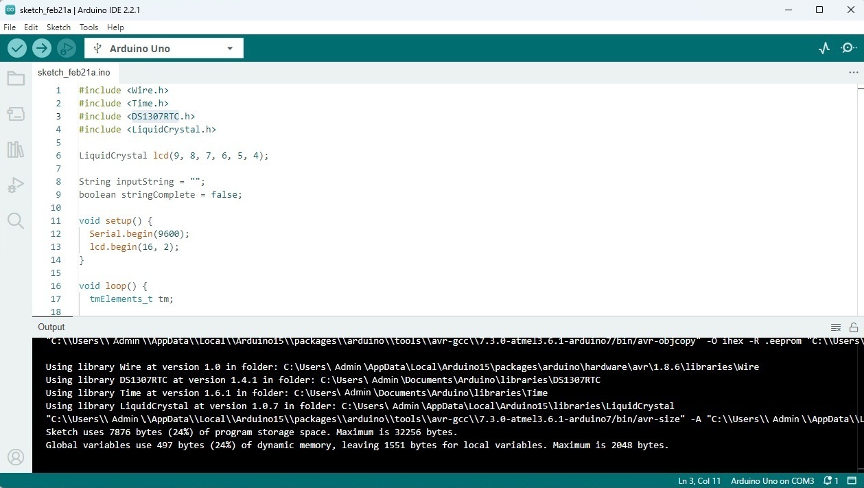
Delete the default template code and paste the full project code below.
Full Source Code
#include <Wire.h>
#include <Time.h>
#include <DS1307RTC.h>
#include <LiquidCrystal.h>
LiquidCrystal lcd(9, 8, 7, 6, 5, 4);
String inputString = "";
boolean stringComplete = false;
void setup() {
Serial.begin(9600);
lcd.begin(16, 2);
}
void loop() {
tmElements_t tm;
if (stringComplete) {
tm.Day = (int(inputString[0]) - 48) * 10 + (int(inputString[1]) - 48);
tm.Month = (int(inputString[3]) - 48) * 10 + (int(inputString[4]) - 48);
tm.Year = CalendarYrToTm(
(int(inputString[6]) - 48) * 1000 +
(int(inputString[7]) - 48) * 100 +
(int(inputString[8]) - 48) * 10 +
(int(inputString[9]) - 48)
);
tm.Hour = (int(inputString[11]) - 48) * 10 + (int(inputString[12]) - 48);
tm.Minute = (int(inputString[14]) - 48) * 10 + (int(inputString[15]) - 48);
tm.Second = (int(inputString[17]) - 48) * 10 + (int(inputString[18]) - 48);
RTC.write(tm);
inputString = "";
stringComplete = false;
}
if (RTC.read(tm)) {
print2digits(tm.Hour, 0, 0);
lcd.print(":");
print2digits(tm.Minute, 3, 0);
lcd.print(":");
print2digits(tm.Second, 6, 0);
print2digits(tm.Day, 0, 1);
lcd.print("/");
print2digits(tm.Month, 3, 1);
lcd.print("/");
lcd.print(tmYearToCalendar(tm.Year));
}
else {
lcd.clear();
lcd.setCursor(0, 0);
if (RTC.chipPresent()) {
lcd.print("DS1307 is stopped");
} else {
lcd.print("DS1307 read error");
}
delay(5000);
}
delay(1000);
}
void print2digits(int number, int col, int row) {
lcd.setCursor(col, row);
if (number >= 0 && number < 10) {
lcd.print("0");
}
lcd.print(number);
}
void serialEvent() {
while (Serial.available()) {
char inChar = (char)Serial.read();
inputString += inChar;
if (inChar == '\n') {
stringComplete = true;
}
}
}
Save the file.
4. Compilation Check
Click the Verify button (✓).
If everything is correct, a successful compilation message will appear at the bottom of the IDE.
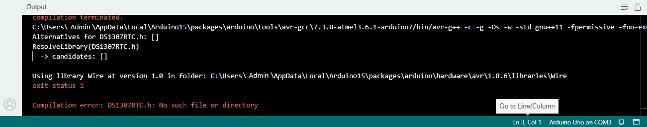
If you see an error such as:
DS1307RTC.h: No such file or directory
it means the required library is not installed.
5. Installing Libraries
Go to:
Sketch → Include Library → Manage Libraries
Search for and install:
- DS1307RTC
- Time
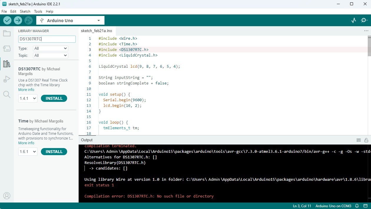
After installation, repeat the compilation step.
6. Uploading the Program
Click the Upload button.
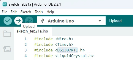
Once completed, the IDE will display:
“Upload complete.”
7. Setting the Time
The current time must be set once.
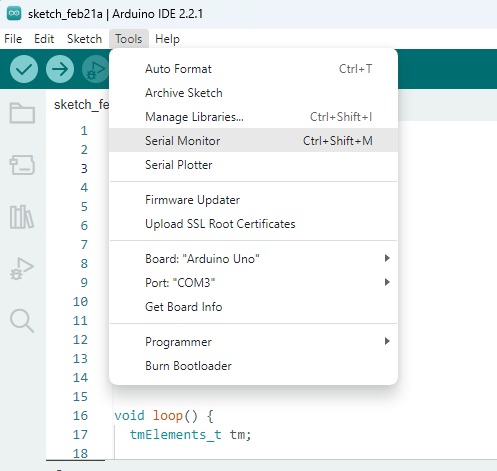
Open:
Tools → Serial Monitor
Set the baud rate to:
9600 baud
Enter the date and time in the following format:
DD/MM/YYYY HH:MM:SS
Example:
21/02/2026 12:09:04
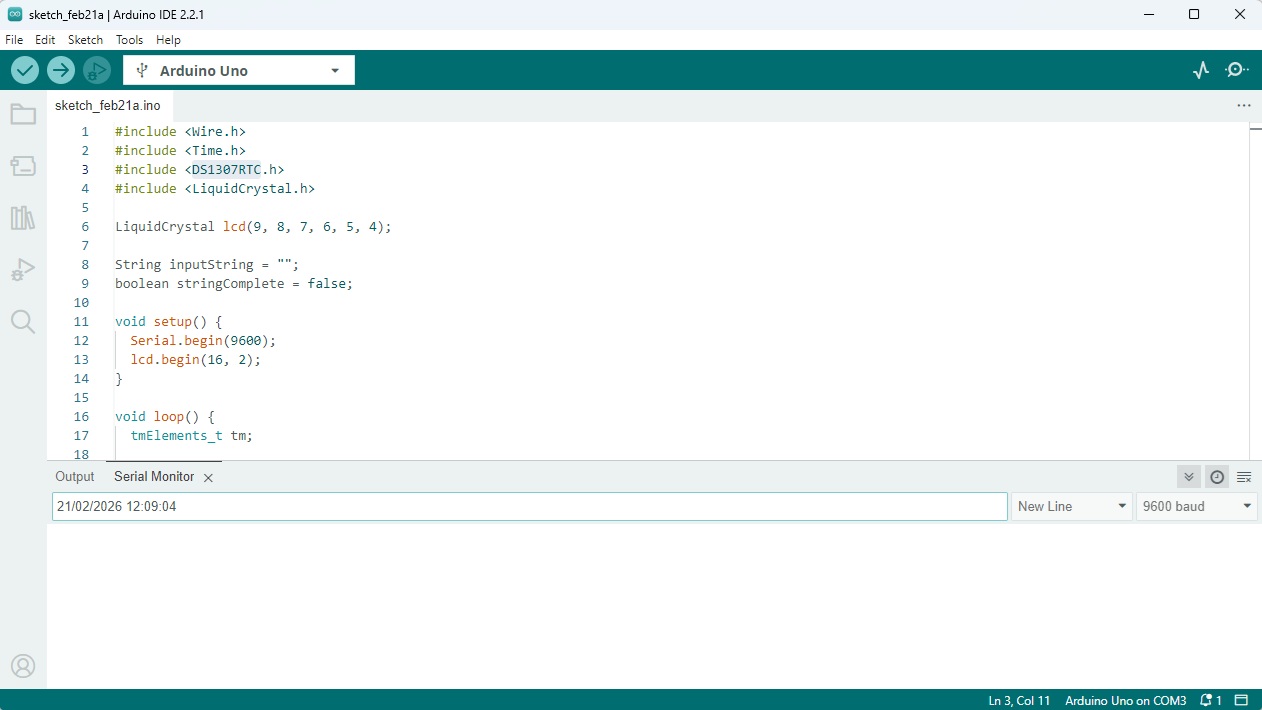
Press Enter.
Arduino will send the data to the RTC module, and the time will be written into the DS1307 internal memory.
From this point on, the module will maintain time autonomously, even if power is disconnected. Resetting the time is only necessary when replacing the battery or performing a full module reset.
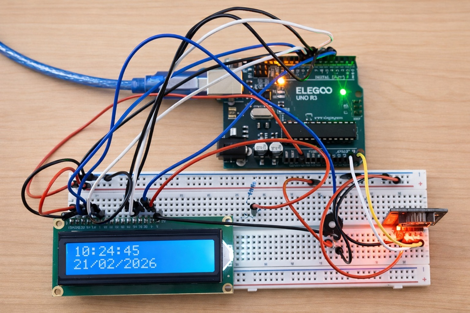
Result
Within a second, the set time will appear on the display.
- First line — current time
- Second line — current date
The display refreshes once per second, while the RTC module keeps time independently of the program delay.
If the module does not respond, an error message will be displayed on the screen.
Practical Notes
- Use short wires.
- Separate power and signal lines.
- Double-check connection polarity.
- If time resets, verify the RTC battery.
Project Expansion
The basic design can be expanded by:
- adding buttons to set time without a computer,
- adding a temperature sensor (e.g., DS18B20),
- implementing an alarm function,
- adding automatic backlight control,
- placing the device in a case,
- using a more accurate DS3231 module.
This project can serve as a foundation for a weather station or an information display.
Continue Your Journey
If you’d like to go further:
🔧 Devices — analysis of real circuits and equipment.
📘 Education — structured materials on electronics fundamentals.
💬 Forum — questions, discussions, and shared experience.
Practice is the best way to deepen understanding.