What Is a Diode and How Does It Work?
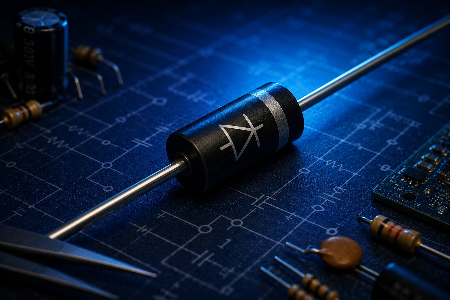
What Is a Diode?
So far, we have learned about resistors and capacitors.
A resistor allows us to limit electric current.
A capacitor can store electrical energy.
Now it is time to introduce another essential electronic component — the diode.
The main characteristic of a diode is that it allows electric current to flow primarily in one direction.
When connected in the correct direction, current can flow through the diode.
If the diode is reversed, it practically stops conducting current.
In simple terms, you can think of a diode as a kind of one-way valve for electric current.
This simple property makes diodes extremely useful in electronic circuits.
How Is a Diode Represented in a Circuit Diagram?
In circuit diagrams, a diode is represented by a special symbol.
It has two terminals:
- anode (A);
- cathode (K).
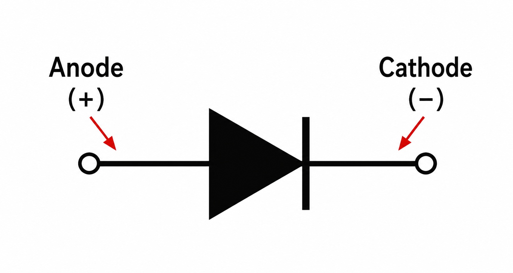
Under normal conducting conditions, conventional current flows through the diode from the anode to the cathode.
This means that the direction in which a diode is connected matters.
If its terminals are reversed, the behavior of the circuit changes.
How Can You Identify the Anode and Cathode on a Real Diode?
Identifying the diode terminals on a circuit diagram is relatively easy.
But how can you tell which terminal is the anode and which is the cathode on a real component?
On most standard rectifier diodes, there is a stripe near one end of the body.
This stripe marks the cathode.
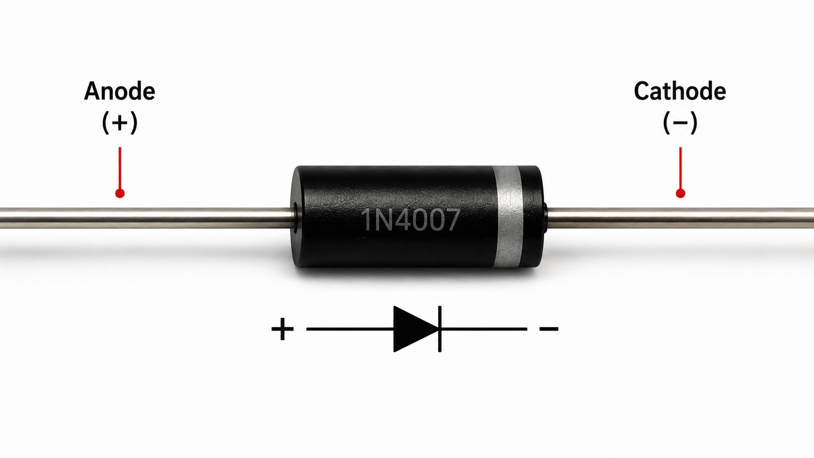
It is worth remembering this simple rule:
The stripe on the body of most standard rectifier diodes marks the cathode.
Before installing a diode in a circuit, always check its orientation.
How Is a Diode Built?
To understand why a diode conducts current primarily in one direction, we need to take a brief look inside the component.
A standard semiconductor diode is made from a semiconductor material, most commonly silicon.
Inside the diode are two semiconductor regions with different properties:
- a P-type region;
- an N-type region.
The boundary between these two regions is called a P-N junction.
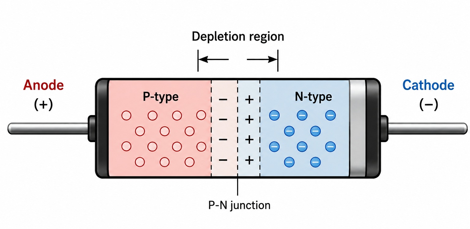
The P-N junction is responsible for the diode's most important characteristic — its behavior changes depending on the direction of the applied voltage.
Semiconductor physics is much more complex than this simplified explanation, but at this stage there is one important principle to remember:
The direction in which a diode is connected matters.
Forward Bias
If the positive terminal of the power supply is connected to the anode and the negative terminal to the cathode, the diode is forward-biased.
In this condition, electric current can flow through it.
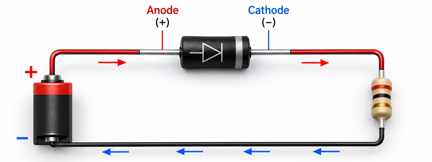
However, a diode should not be considered a perfect conductor.
When current flows through it, there is a certain voltage drop across the diode.
For a typical silicon diode, this voltage drop is often around 0.6–0.7 V.
For example, if there is approximately 5 V before the diode, the voltage after it under load may be roughly:
5 V − 0.7 V ≈ 4.3 V
The exact value depends on the type of diode, the amount of current flowing through it, and its temperature.
Reverse Bias
Now let's reverse the diode.
The anode is connected toward the lower potential and the cathode toward the higher potential.
This is known as reverse bias.
In this condition, a standard diode conducts practically no current.
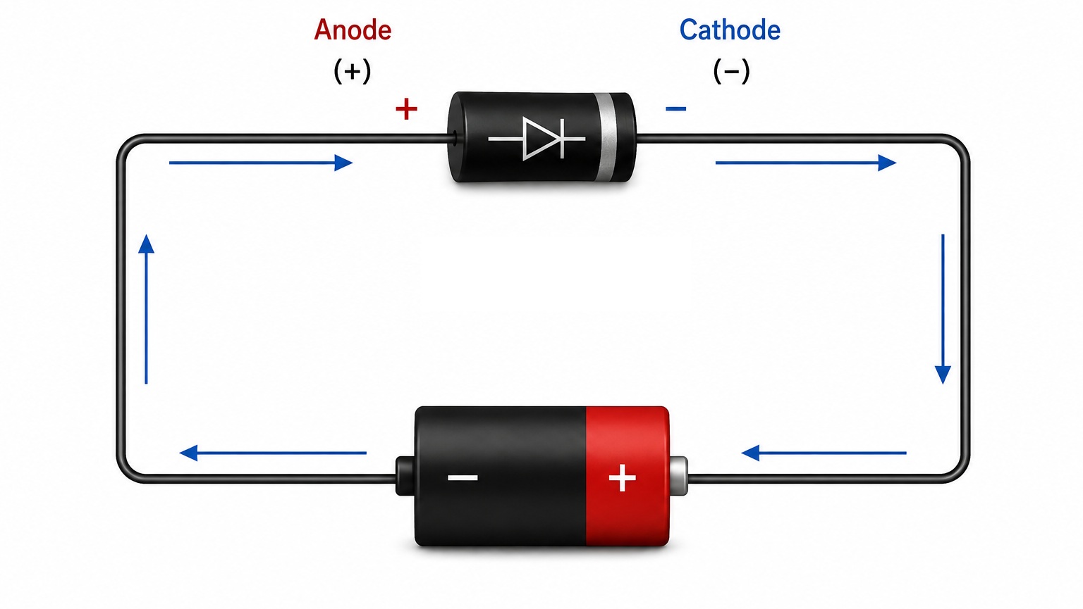
This is what allows a diode to control the direction of current flow in an electrical circuit.
However, every diode has a maximum allowable reverse voltage.
If this voltage is exceeded, the diode may enter breakdown and can be damaged.
Therefore, we should not assume that a diode can block an unlimited reverse voltage.
Experiment — Let's Test a Diode
Now let's test the most important property of a diode in practice.
For this experiment, we will need:
- a DC power source;
- a standard diode;
- an LED;
- a current-limiting resistor;
- connecting wires.
Let's build a simple circuit.
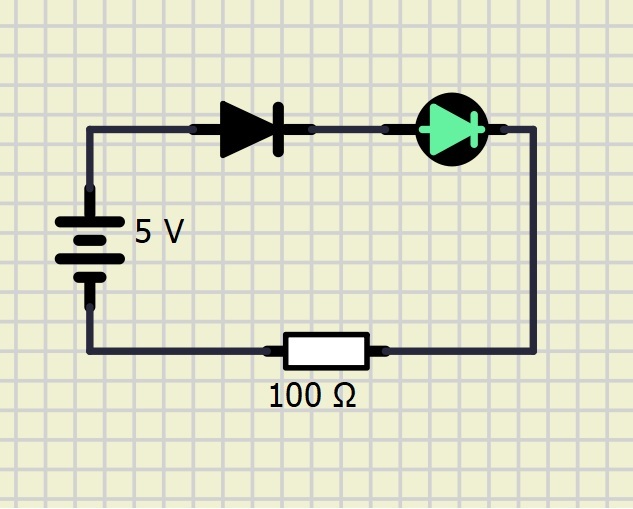
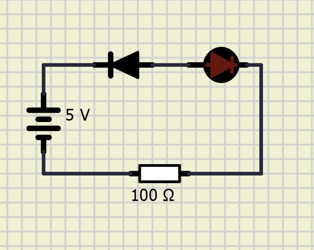
First, connect the diode in the forward direction.
When the power is switched on, current flows through the circuit and the LED lights up.
Now disconnect the power and reverse the standard diode.
When the power is switched on again, the LED should no longer light up.
Nothing else in the circuit has changed.
The only difference is the orientation of the diode.
This simple experiment clearly demonstrates its most important property:
A diode allows current to flow in one direction while blocking it in the opposite direction.
Testing a Diode with a Multimeter
Many digital multimeters have a special mode designed specifically for testing diodes.
It is usually marked with the diode symbol.
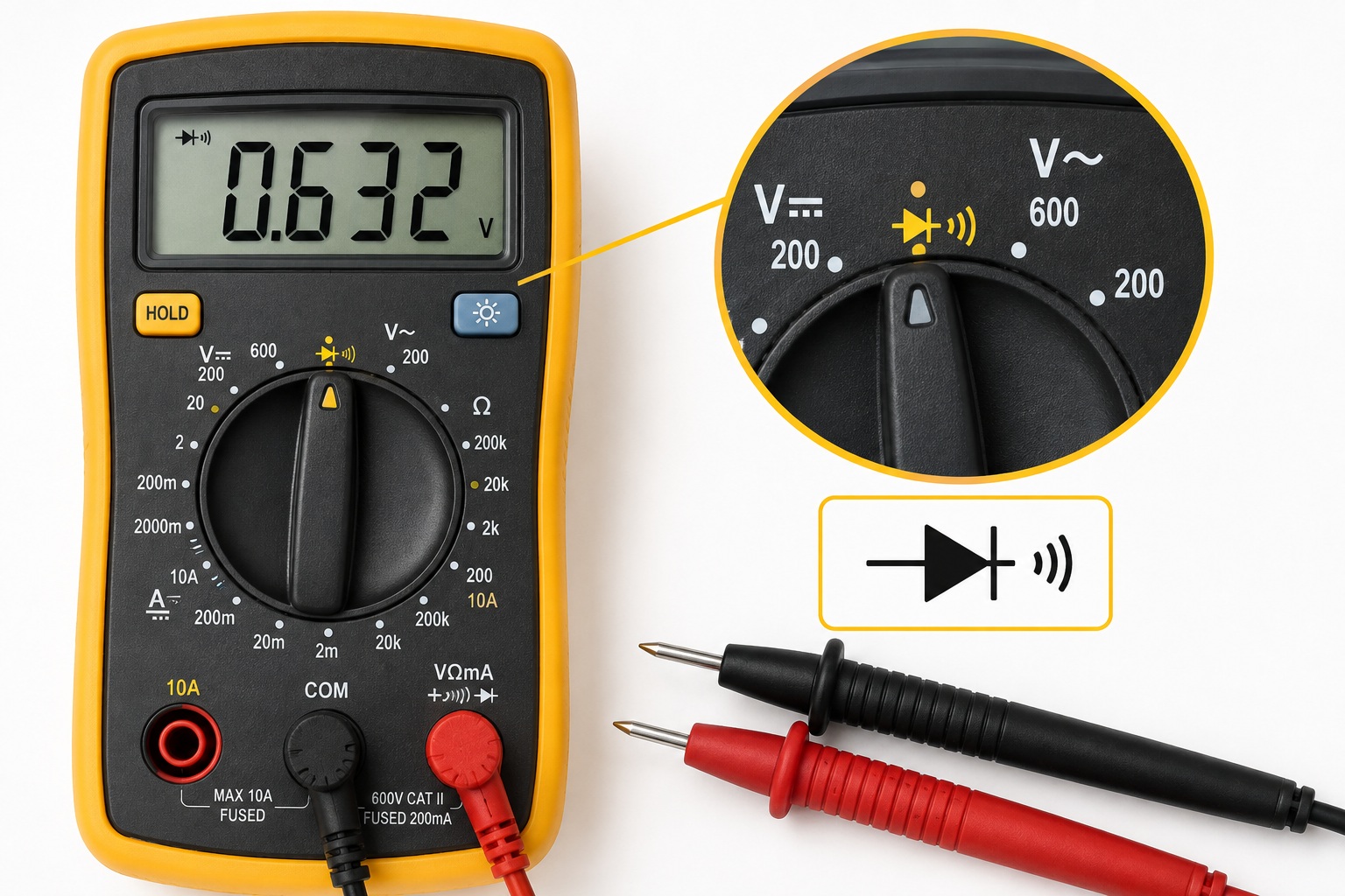
Connect the red probe to the anode and the black probe to the cathode.
For a working silicon diode, the multimeter will typically display a forward voltage drop of approximately 0.5–0.8 V.
Now reverse the probes.
A working standard diode should conduct practically no current in the reverse direction, so the multimeter will usually display OL or another indication of an open circuit.
This method allows us not only to check whether a diode is working correctly, but also to identify its anode and cathode.
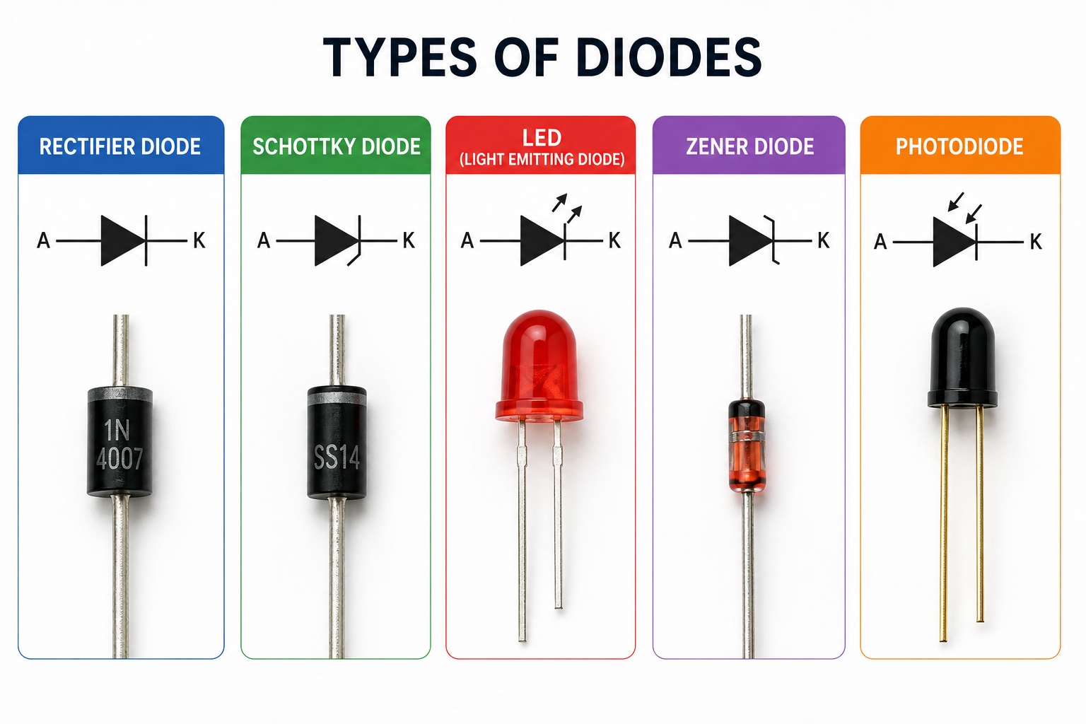
What Types of Diodes Are There?
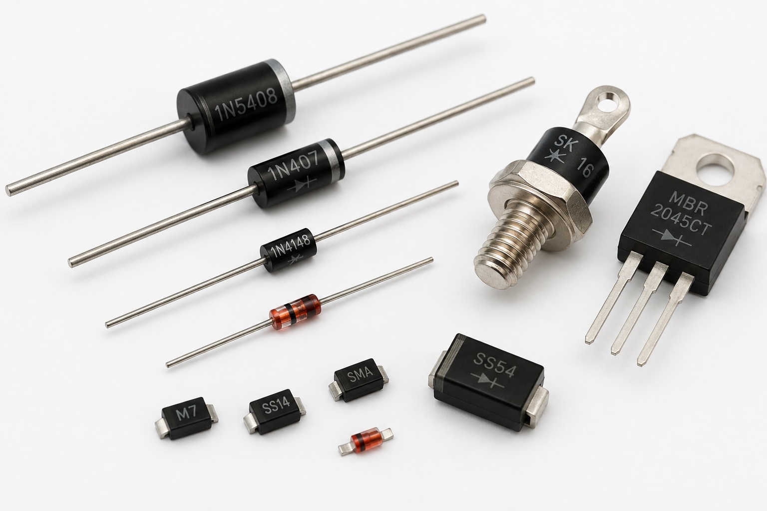
There are many different types of diodes used in electronics.
They operate according to similar basic principles, but each type is designed for different applications.
Rectifier Diodes
Rectifier diodes are among the most common types of diodes.
They are widely used in power supplies, chargers, and other circuits where current direction must be controlled or AC voltage needs to be rectified.
A well-known example is the 1N400x series.
Schottky Diodes
Schottky diodes have a lower forward voltage drop than typical silicon P-N junction diodes.
Under suitable operating conditions, the forward voltage drop of many Schottky diodes may be around 0.2–0.4 V.
This can reduce power losses across the diode.
For this reason, Schottky diodes are commonly used in power supplies and low-voltage electronic circuits.
LEDs
We are already familiar with LEDs.
LED (Light-Emitting Diode) is, as the name suggests, a type of diode that emits light.
Like other diodes, an LED conducts current primarily in one direction, but it also produces light when operating correctly.
Zener Diodes
A Zener diode is a special type of diode designed to operate in a controlled reverse-breakdown region.
This property allows it to be used for voltage limiting and voltage regulation.
We will take a closer look at Zener diodes in a separate article.
Photodiodes
A photodiode responds to incoming light.
Instead of producing light like an LED, it can convert incoming light into an electrical signal.
Photodiodes are used in sensors, communication systems, measuring equipment, and many other electronic devices.
Where Are Diodes Used?
The diode's simple ability to behave differently depending on current direction makes it useful for a huge number of practical applications.
Let's look at several examples.
Reverse-Polarity Protection
Imagine an electronic device powered by a battery.
If the positive and negative terminals are accidentally connected the wrong way around, some electronic components may be damaged.
A diode can provide a very simple form of protection against this mistake.
With the correct polarity, current flows through the diode and the device operates normally.
If the polarity is reversed, the diode blocks the current.
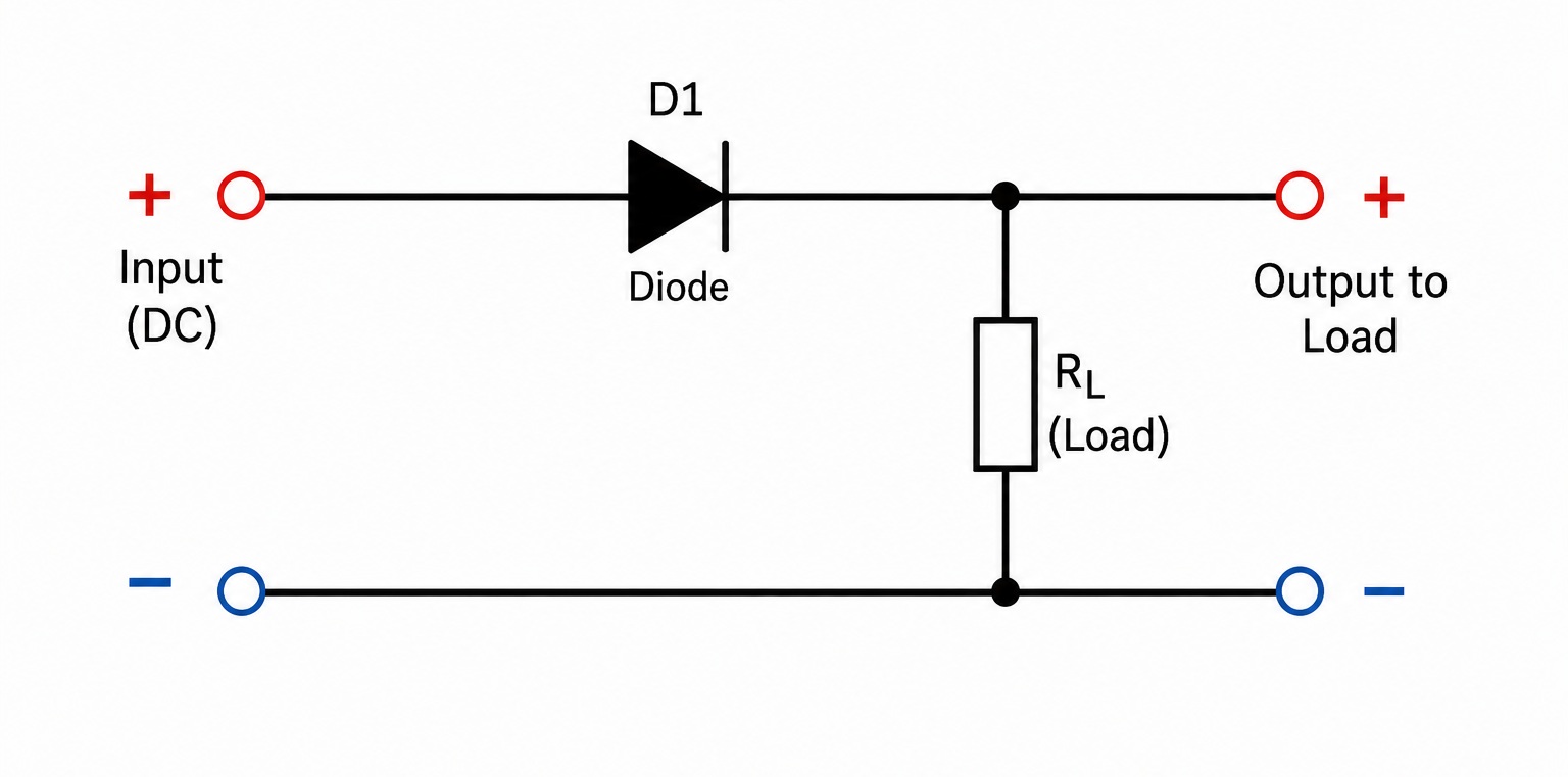
This solution is very simple, but it has one disadvantage — some of the supply voltage is lost across the diode itself.
We will return to reverse-polarity protection in a separate article and look at several different ways to implement it.
Converting AC Voltage to DC
A diode can allow only one part of an alternating waveform to pass through the circuit.
This makes it possible to use a diode for rectification — converting alternating voltage into a unidirectional voltage.
By using several diodes, we can build a more effective circuit known as a bridge rectifier.
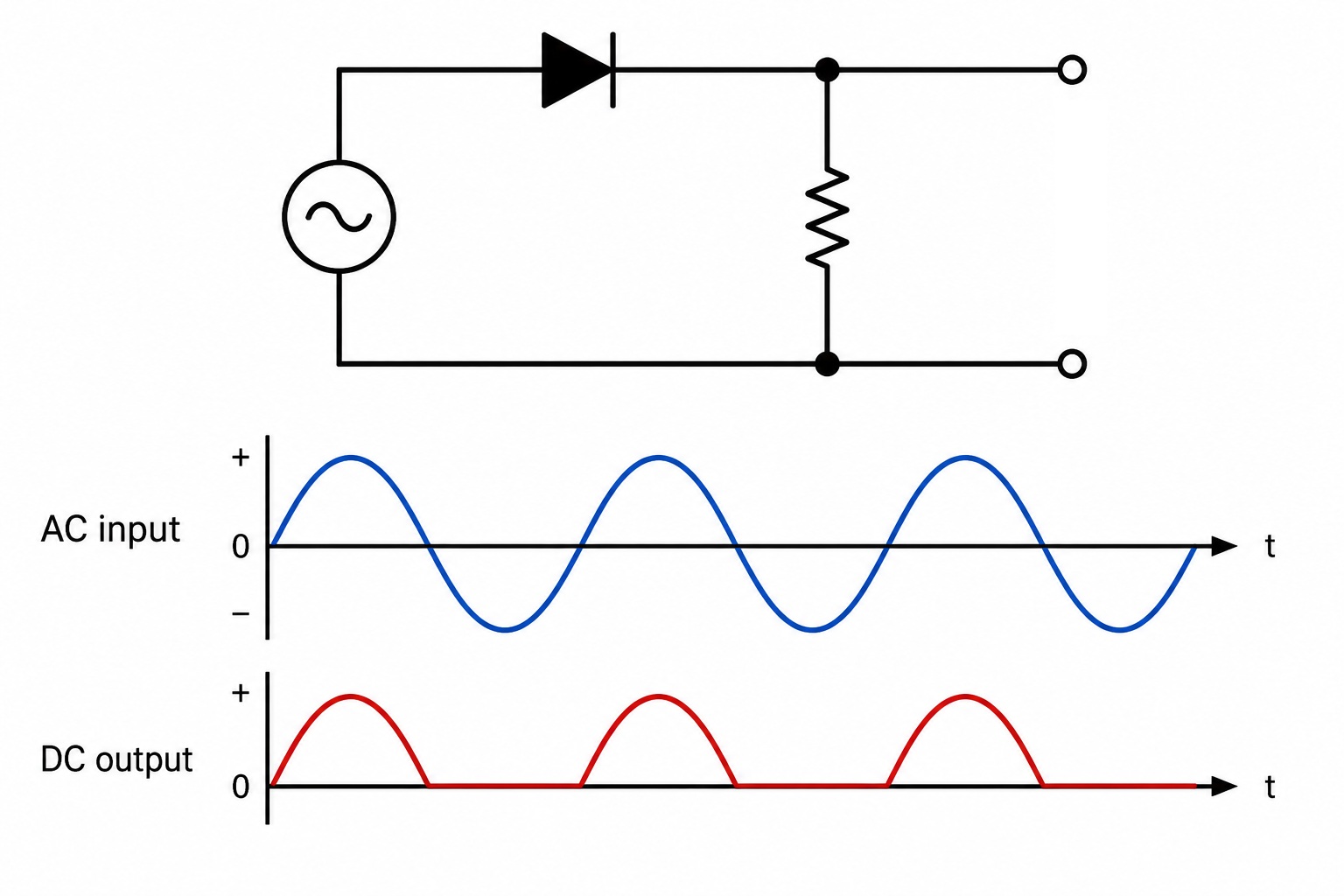
Diode rectifiers are found in a huge number of power supplies.
We will explore this topic in more detail in a separate article.
Protection When Working with Relays and Other Coils
Coils have an interesting property.
When the current flowing through a coil is suddenly switched off, the coil can generate a short high-voltage pulse.
This pulse can damage the controlling transistor or other electronic components.
A diode connected in parallel with the coil in the correct direction provides a safe path for the current and helps suppress this voltage spike.
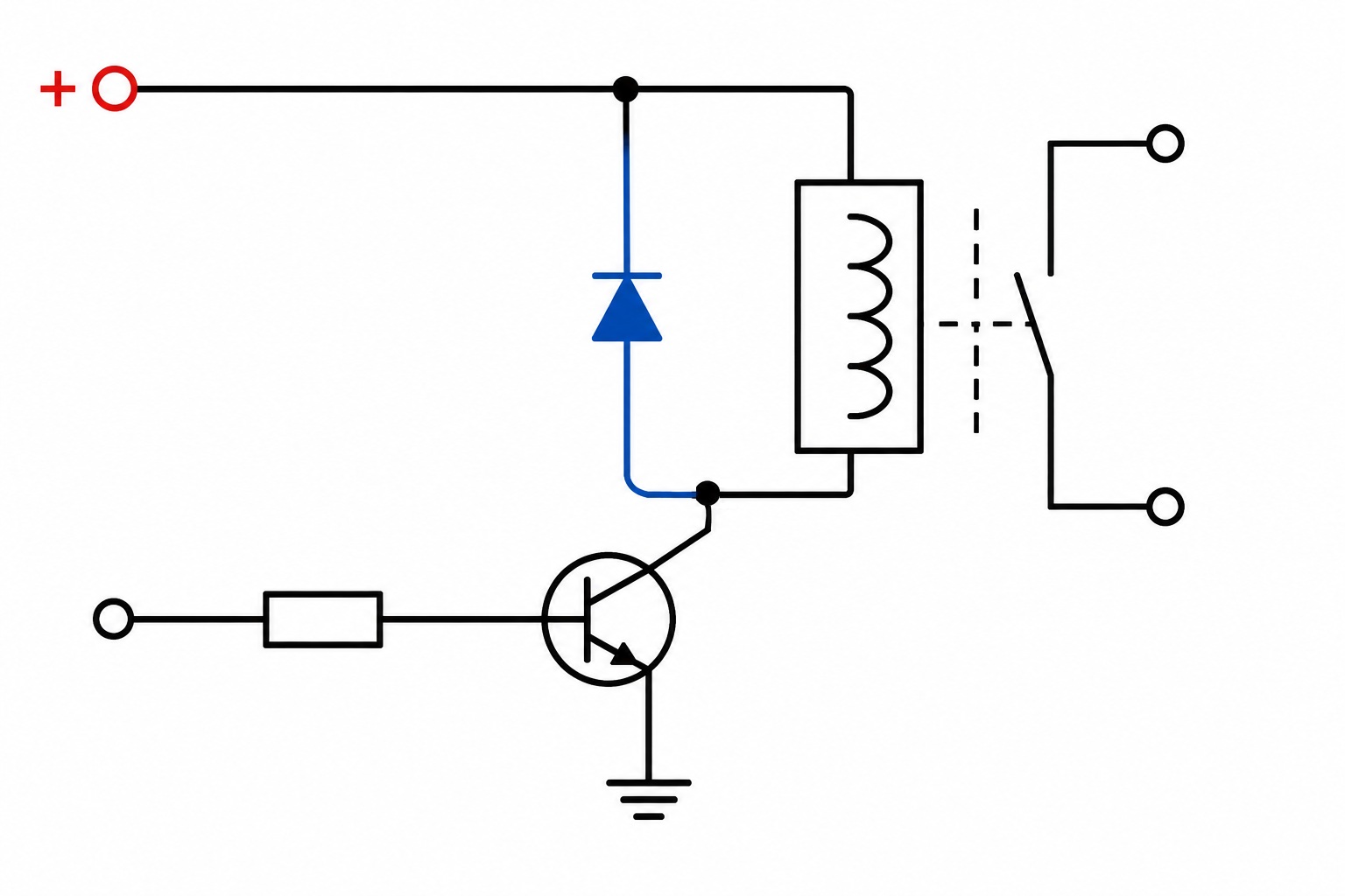
These protective diodes are very commonly used in circuits that control relays, solenoids, and electric motors.
We will understand the reason for this voltage spike in more detail later, when we learn about inductance and self-induction.
Automatic Power Source Selection
There is another very interesting application of diodes.
Imagine a device that can operate from two different power sources.
Each power source can be connected to the same load through its own diode.
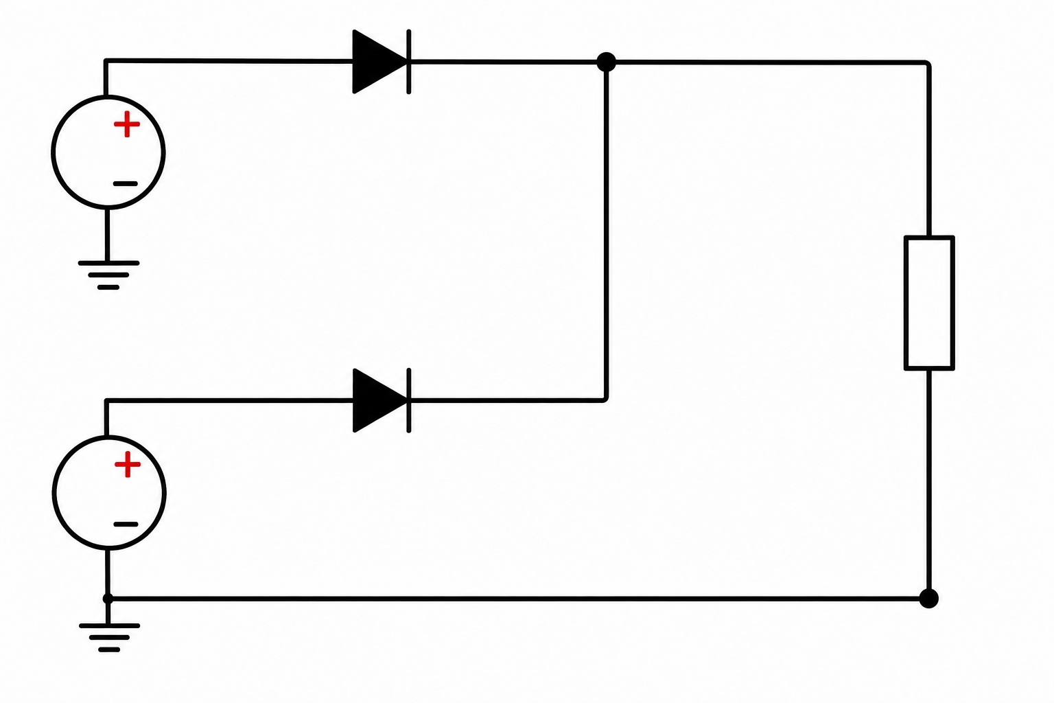
In simplified form, the circuit looks like this:
Source 1 ──>|──┐
D1 │
├──── Device
D2 │
Source 2 ──>|──┘
If one source has a higher voltage, it will usually supply most or all of the power to the device.
At the same time, the diodes prevent current from freely flowing backward from one power source into the other.
If the main power source is disconnected, the second source can automatically take over.
This method of connecting power sources is known as diode ORing.
If the voltages of the two sources are very close, the actual current distribution becomes more complicated and depends on the characteristics of the diodes being used.
For understanding the basic principle, however, we can think of the device as being powered primarily by the source with the higher voltage.
A Familiar Example — A Laptop
The idea of automatic power source selection is easy to understand using an ordinary laptop as an example.
A laptop can receive power from:
- an external power adapter;
- its built-in battery.
When the power adapter is connected, the laptop can receive energy from the external power source while the battery is charged when necessary.
When the adapter is disconnected, the laptop automatically continues operating from its battery.
The user does not need to manually switch between the two power sources.

It is important to understand that modern laptops generally do not perform this task using just two ordinary diodes.
Laptop power systems are much more sophisticated and typically use dedicated power-management controllers and MOSFET transistors to manage the flow of energy more efficiently.
However, a simple circuit with two diodes is a good way to demonstrate the basic principle of power-source isolation and automatic source selection.
Common Beginner Mistakes
Mistake #1. Treating a Diode as a Perfect Conductor
Even when a standard diode is conducting, there is a voltage drop across it.
For a typical silicon diode, this is often around 0.6–0.7 V, although the value is not perfectly constant.
This voltage drop must be taken into account when designing a circuit.
Mistake #2. Connecting a Diode in Either Direction
A diode is a polarized component.
Swapping the anode and cathode changes the way the circuit operates.
Before installing a diode, always check the markings on its body or consult its datasheet.
Mistake #3. Assuming a Diode Can Withstand Any Reverse Voltage
A standard diode blocks current in the reverse direction only up to a certain voltage.
If its maximum reverse-voltage rating is exceeded, breakdown may occur and the component can be damaged.
Mistake #4. Assuming All Diodes Are the Same
Rectifier diodes, Schottky diodes, LEDs, and Zener diodes are designed for different purposes.
They differ in maximum current, voltage ratings, switching speed, forward voltage drop, and many other characteristics.
For this reason, a diode should never be selected based only on its appearance.
Key Points to Remember
- A diode conducts electric current primarily in one direction.
- A diode has an anode and a cathode.
- The stripe on the body of most standard rectifier diodes marks the cathode.
- A forward-biased diode conducts current.
- A reverse-biased standard diode conducts practically no current as long as its maximum reverse voltage is not exceeded.
- There is a voltage drop across a conducting diode.
- For a typical silicon diode, this voltage drop is often around 0.6–0.7 V.
- A diode can be tested using the diode-test mode of a multimeter.
- Different types of diodes are designed for different applications.
- Diodes are used for rectification, circuit protection, protection of inductive loads, and automatic power source selection.
Conclusion
A diode is a small and seemingly simple electronic component.
However, its ability to behave differently depending on the direction of current flow is the foundation of an enormous number of electronic circuits.
We now know why the orientation of a diode matters, how the anode and cathode differ, why there is a voltage drop across a conducting diode, and how to test a diode with a multimeter.
We have also seen how one basic property can solve very different problems — from protecting a device against reversed power polarity to automatically selecting between multiple power sources.
And this is only the beginning.
In future articles, we will explore some of these applications in much more detail.
What's Next?
We now know that a diode can prevent current from flowing in an unwanted direction.
Next, we will put this property to practical use.
In the next article, we will look at reverse-polarity protection — what can happen when a power supply is connected incorrectly and how an ordinary diode can protect a circuit from this mistake.
Later, we will also explore bridge rectifiers, Zener diodes, and other interesting applications of diodes.
You can also:
🔧 visit the “Devices” section to see practical applications;
📘 continue learning in the “Education” section;
💬 ask questions or join the discussion on the Forum.