What Is an LED and How to Connect It
1. What We Are Going to Do
In this lesson, we will познакомимся with the LED — one of the most popular components in modern electronics.
We will perform several simple experiments:
• connect an LED to batteries
• test different resistors
• connect an LED to USB
• build a small LED lighting setup using several LEDs
We will also learn:
• how an LED differs from a light bulb
• what polarity means
• why a resistor is needed
• why an LED can burn out
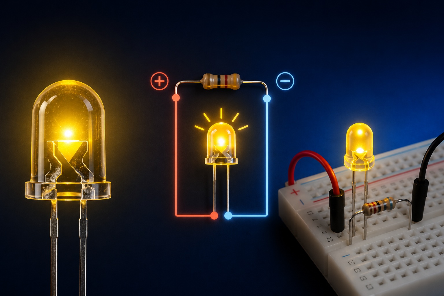
2. What Is an LED
An LED is an electronic component that emits light when electric current flows through it.
LED stands for:
Light Emitting Diode
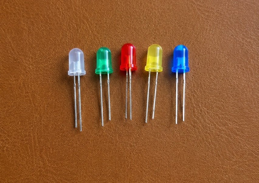
LEDs come in different sizes, colors, and shapes.
In this lesson, we will use 5 mm LEDs from an Arduino kit:
• red
• green
• blue
• yellow
• transparent
3. What an LED Consists Of
A typical LED consists of:
• a plastic корпус
• a semiconductor crystal
• metal leads
• a reflector
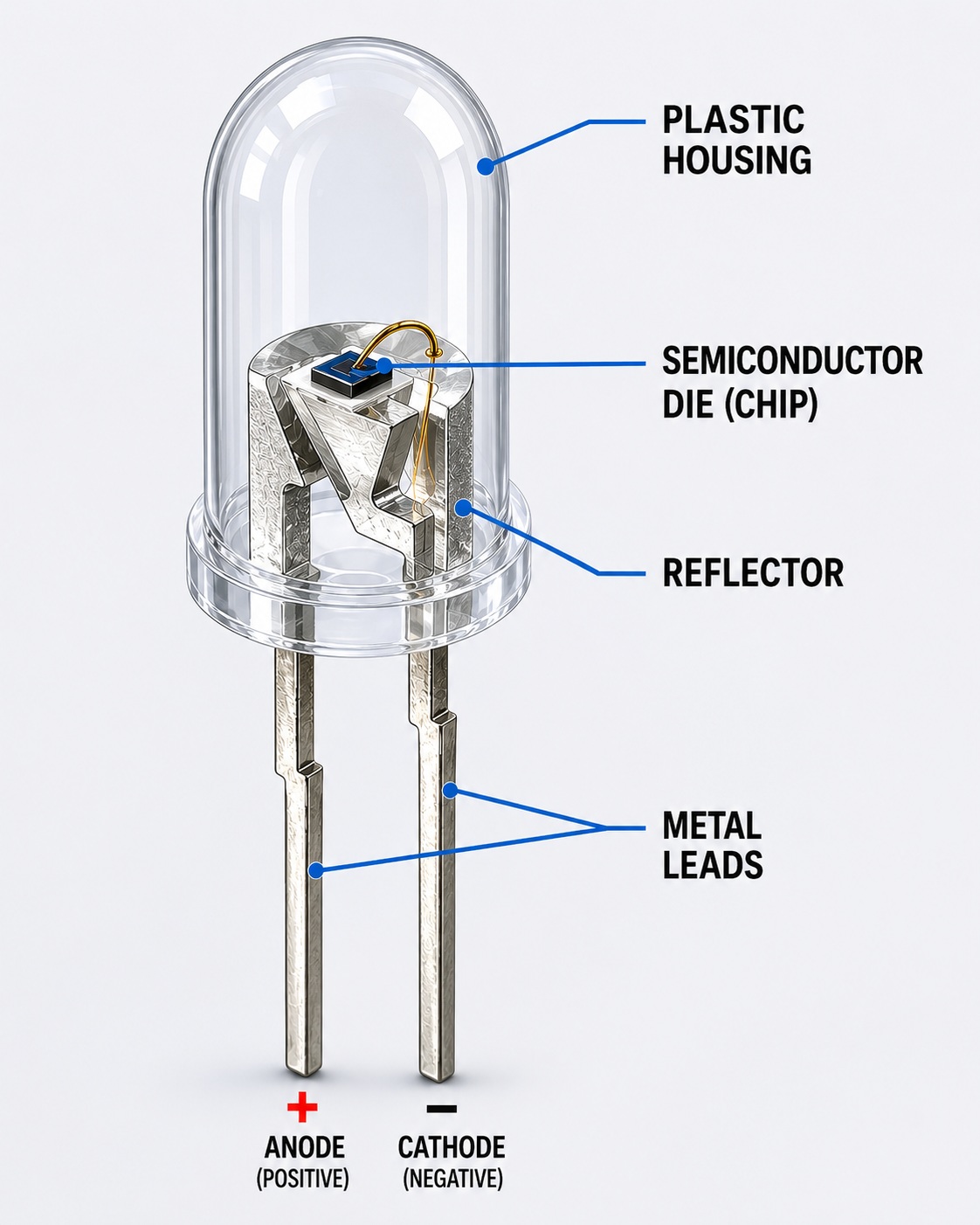
An LED has two leads:
• anode (+)
• cathode (-)
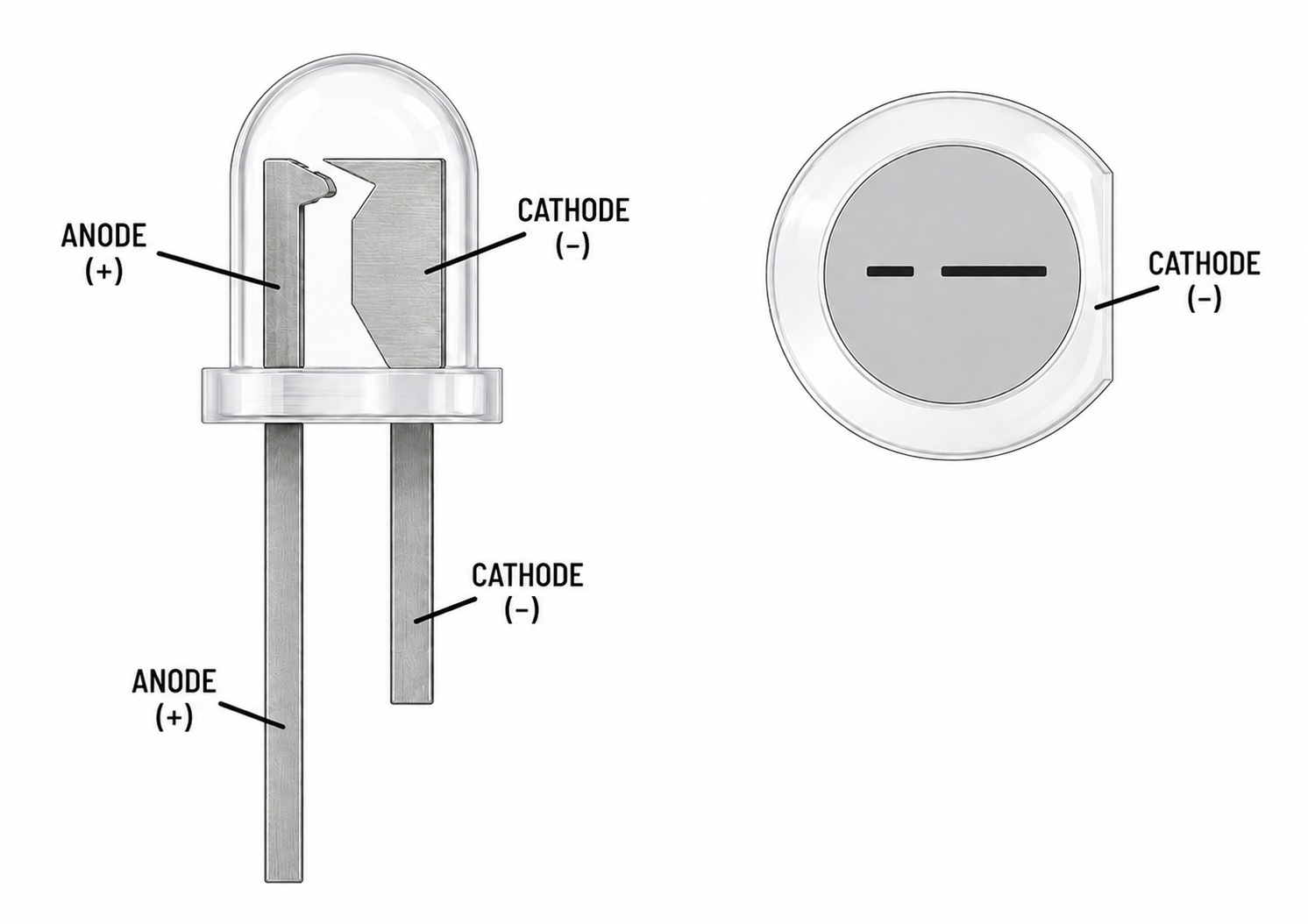
Unlike a regular light bulb, an LED has polarity.
If connected incorrectly, it will not light up.
4. How to Determine LED Polarity
Usually:
• the longer leg is the positive side (anode)
• the shorter leg is the negative side (cathode)
Many LEDs also have a flat side on the body indicating the negative side.
5. How an LED Differs from a Light Bulb
An incandescent light bulb glows because a metal filament inside becomes extremely hot.
An LED works in a completely different way.
It does not need a glowing hot filament, therefore it:
• consumes less power
• barely heats up
• lasts much longer
• shines brighter with lower power consumption
When connected correctly, an LED can work for a very long time — much longer than a regular light bulb.
6. Power from Batteries
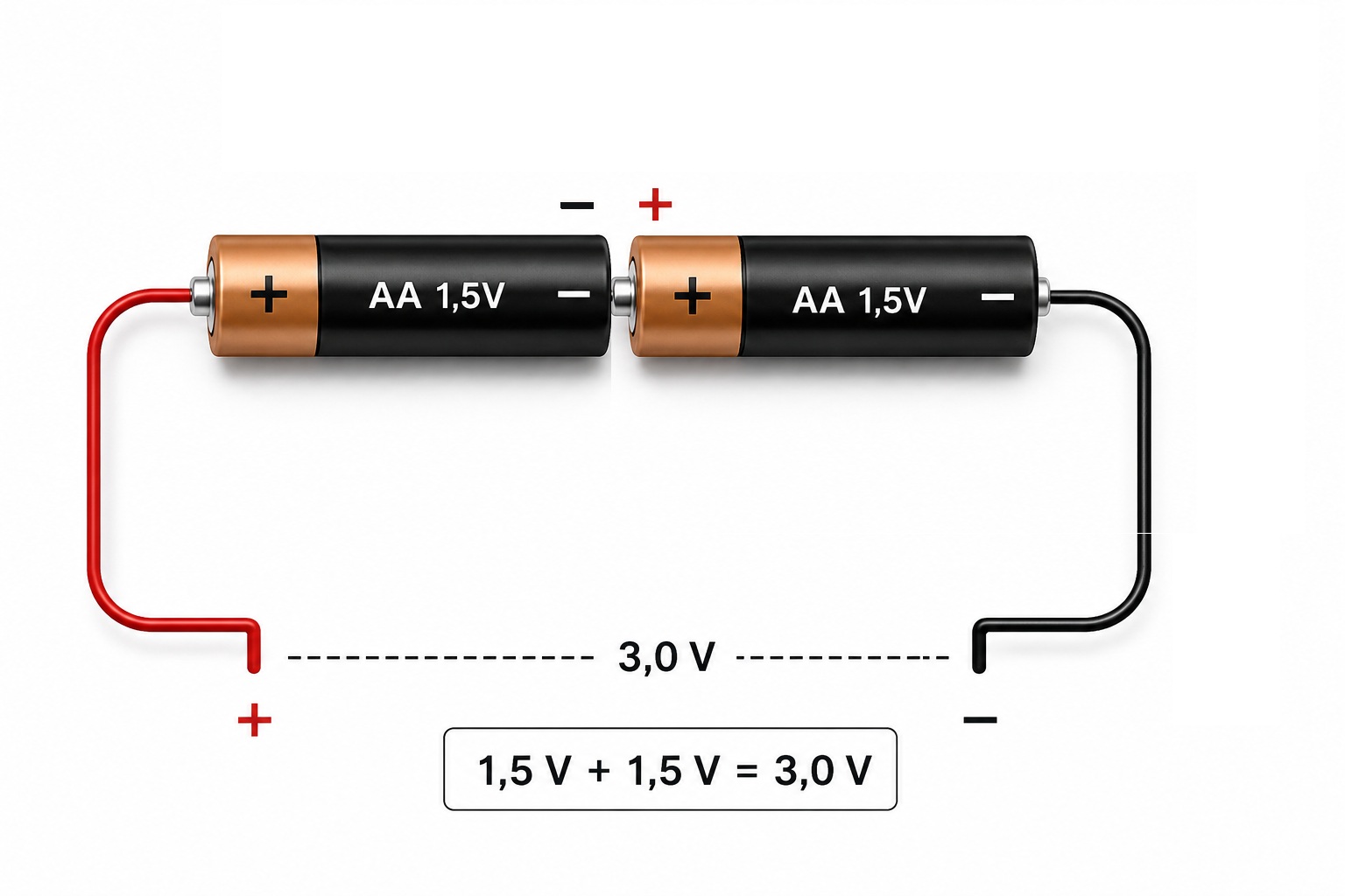
One AA or AAA battery usually has a voltage of:
1.5 V
If we connect two batteries in series:
• the voltage adds up
• 1.5 V + 1.5 V = 3 V
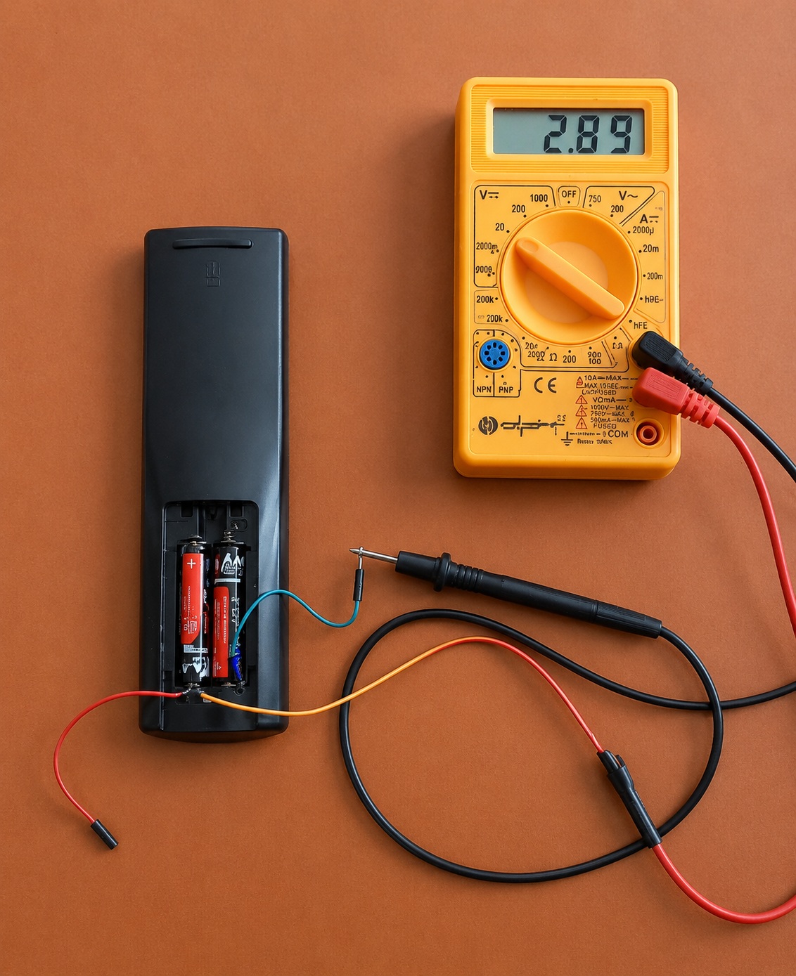
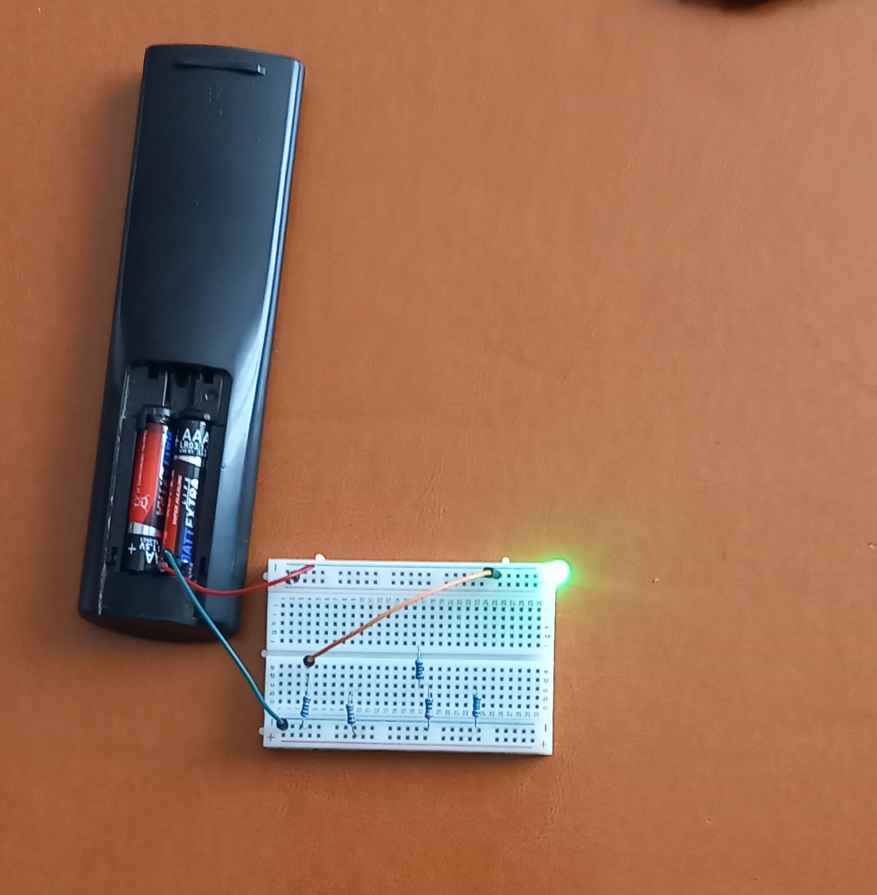
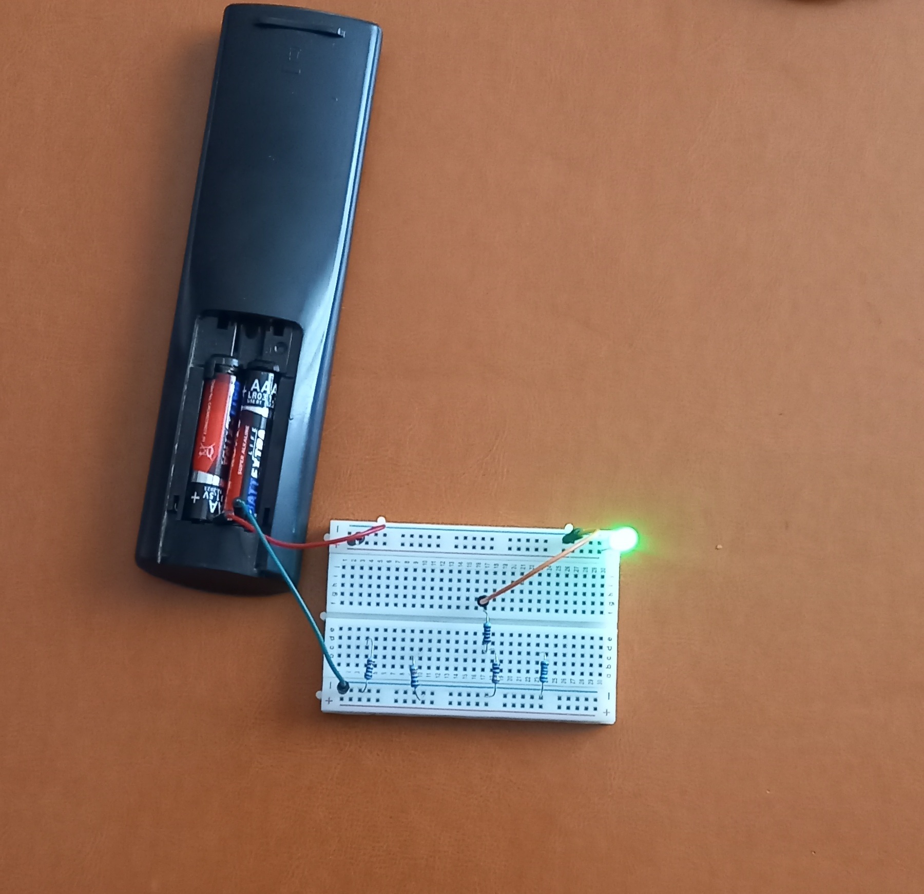
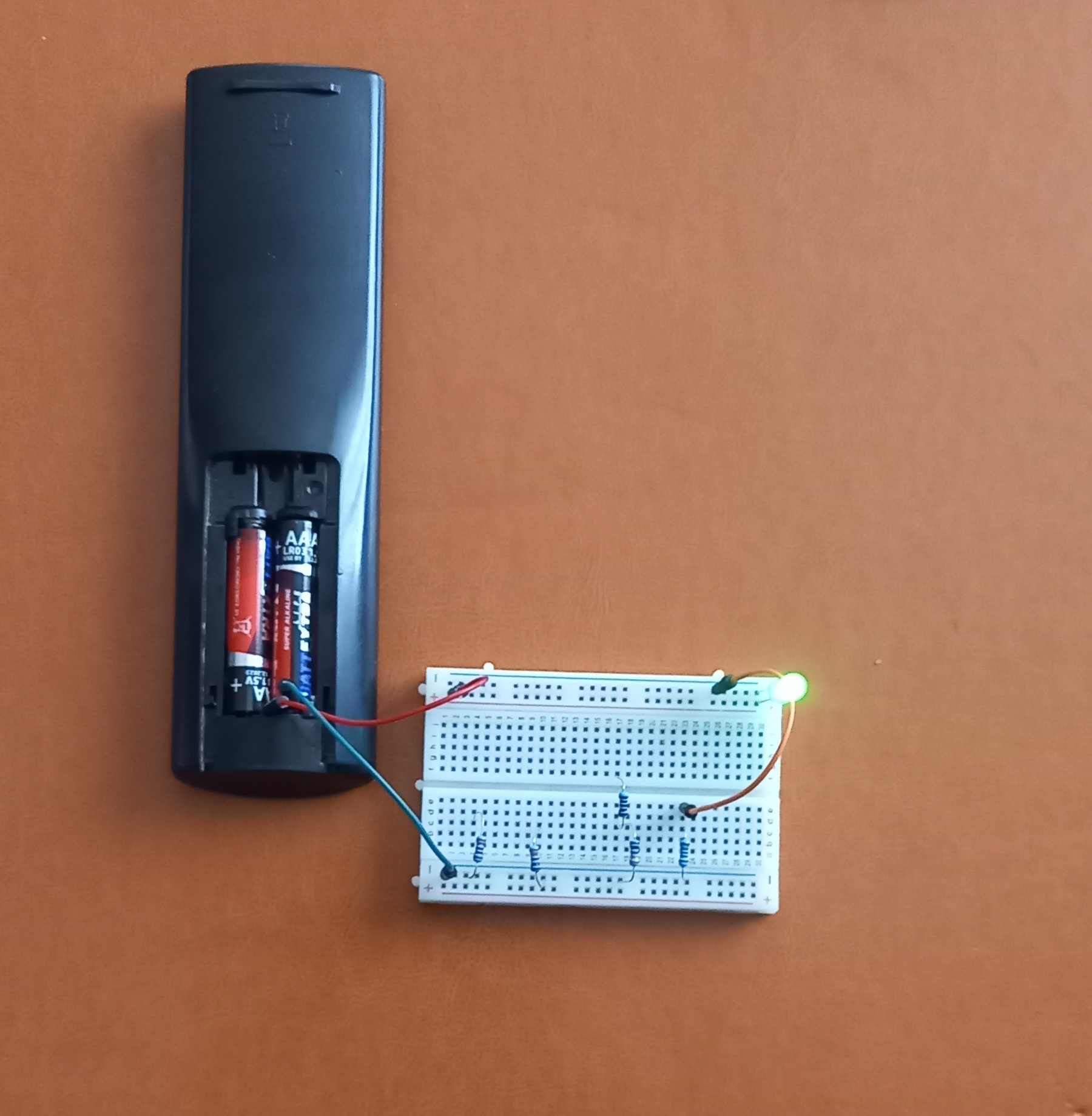
If you do not have a battery holder for two batteries, you can use a remote control — that is exactly what I used. Simply connect two wires to the plus and minus terminals and measure the voltage using a multimeter.
If batteries are connected in parallel, the voltage remains the same — 1.5 V.
This type of connection is usually used to increase operating time.
7. First Experiment — LED Without a Resistor
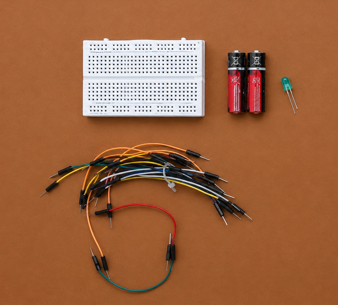
For the first experiment we will need:
• two batteries
• an LED
• a breadboard
• jumper wires
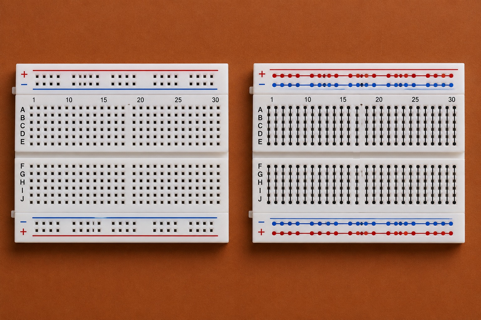
What Is a Breadboard
A breadboard allows you to build electronic circuits without soldering.
Components and wires are simply inserted into the holes.
Inside the breadboard, many holes are already connected with metal contacts.
Connection
We connect:
• battery positive to the LED anode
• battery negative to the LED cathode
If everything is connected correctly, the LED will light up.
Some LEDs can work from 3 V even without a resistor.
However, this connection is not considered correct because the current through the LED may become too large, causing the LED to fail very quickly.
Therefore, this experiment should only be performed briefly to avoid burning out the LED.
8. Why a Resistor Is Needed
An LED is very sensitive to current.
If the current is too high:
❌ the LED overheats
❌ it glows too brightly
❌ its lifespan decreases
❌ the LED may burn out
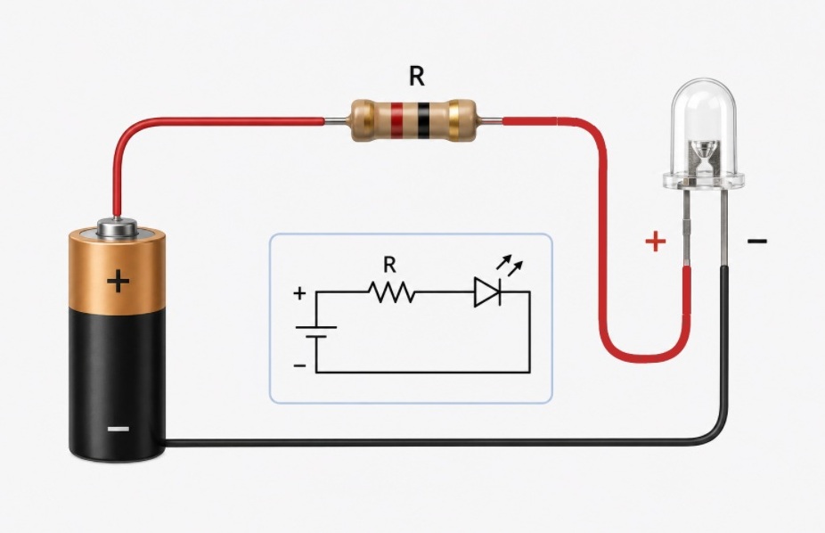
That is why LEDs are usually connected together with a resistor.
The resistor limits the current and protects the LED.
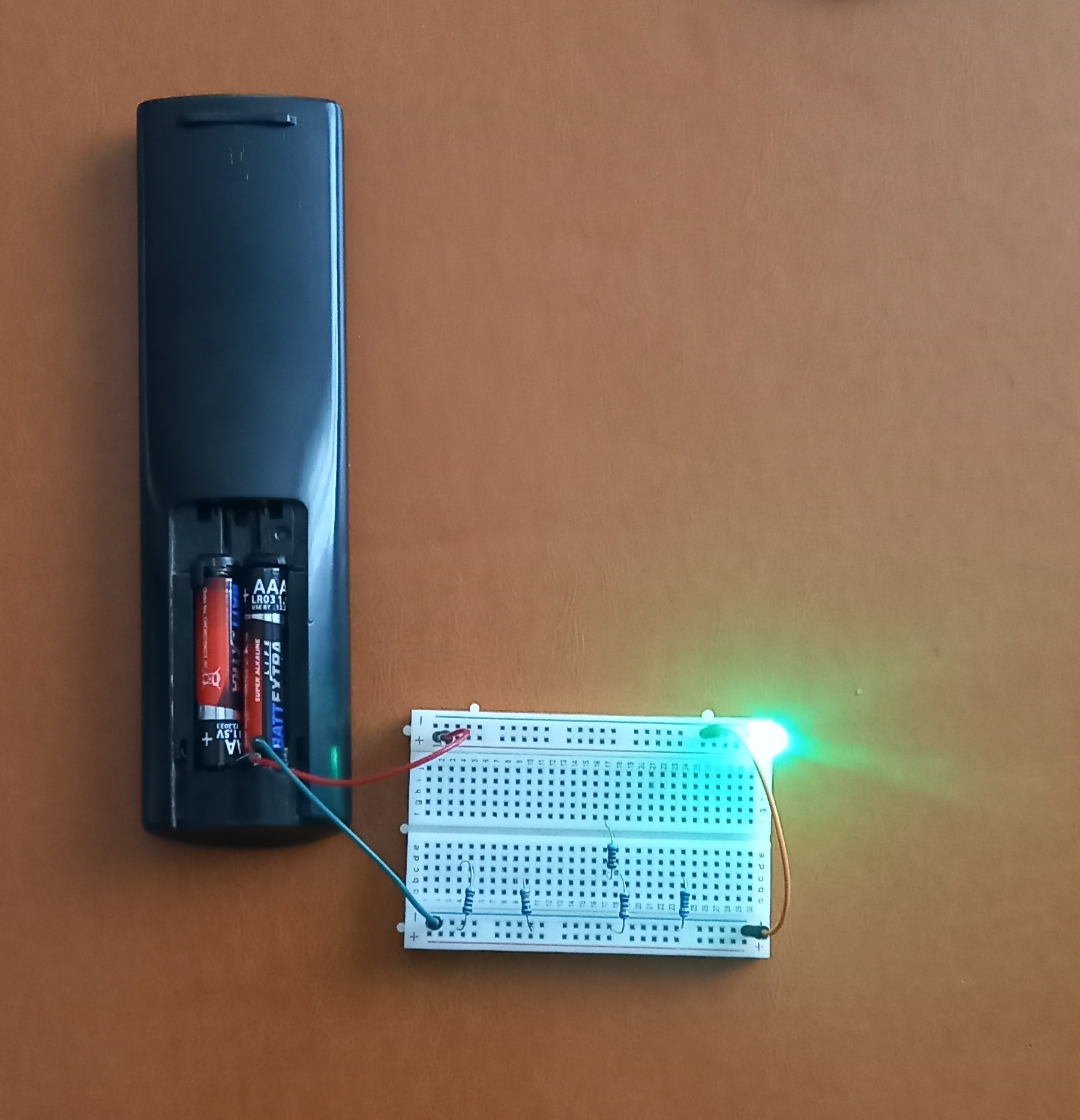
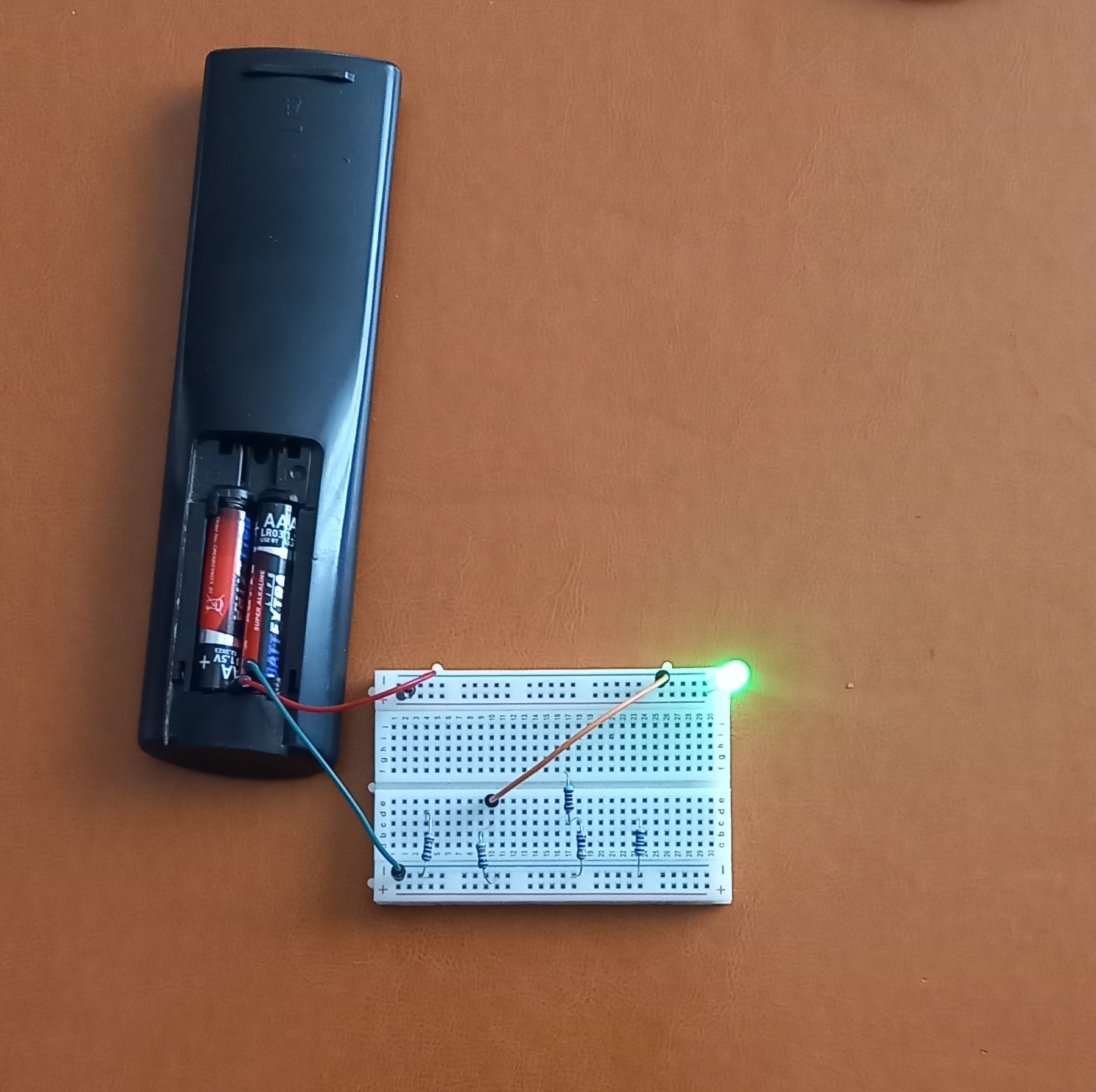
9. Experiment with Different Resistors
Now let us try connecting the LED through different resistors.
220 Ω
The LED shines very brightly
330 Ω
The brightness becomes slightly lower.
430 Ω
Since I did not have a 470 Ω resistor, I connected two resistors in series: 330 Ω and 100 Ω. The total resistance became 430 Ω.
The light becomes softer.
1 kΩ
The LED becomes noticeably dimmer.
Conclusion
The larger the resistance:
👉 the smaller the current
👉 and the dimmer the LED glows
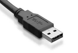
10. Power from USB
A standard USB connector usually provides:
5 V
That is why USB is often used to power small electronic devices and experiments.
⚠ Important
When connecting an LED to USB power, never connect the LED directly without a resistor.
USB can provide much more current than regular batteries.
Because of this, the LED may instantly burn out.
11. LED + Resistor + USB
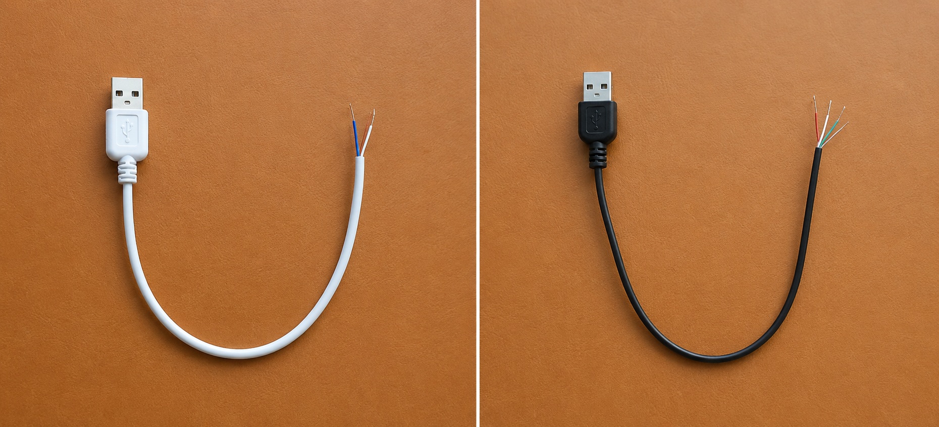
A USB cable may contain two, four, five, or even more wires.
Depending on the cable type, the number of wires may vary. For example, a phone charging cable usually contains two wires — positive and negative 5 V power lines. USB 2.0 cables contain four wires: positive, negative, data+, and data-.
A multimeter should be used to identify the correct power wires.
Now we connect:
• USB 5 V
• resistor
• LED
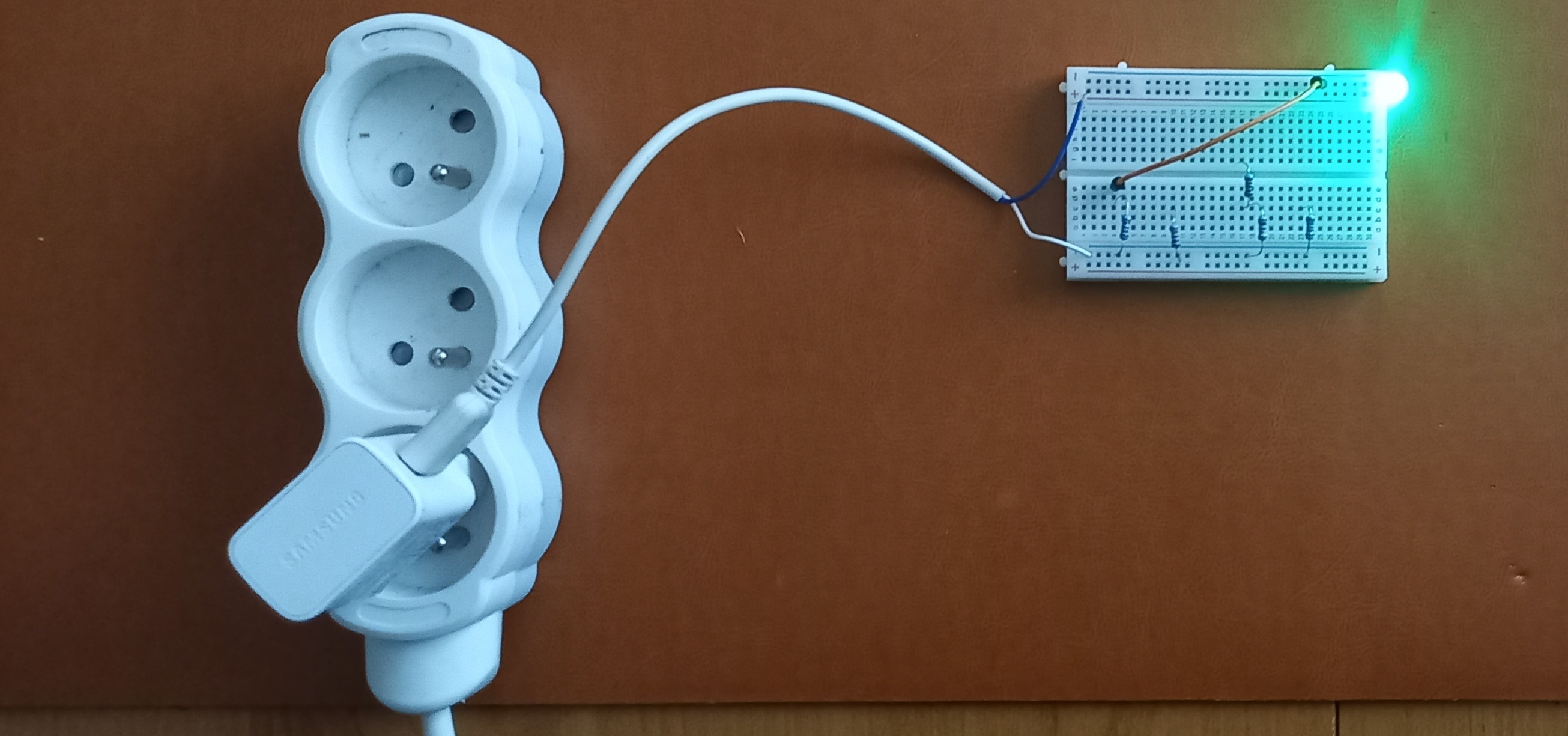
This connection is already correct and safe.
12. Multiple LEDs from USB
Several LEDs can be powered from a single USB port at the same time.
However, it is very important to remember:
👉 each LED should have its own resistor.
Example of a correct connection:
USB → resistor → LED
USB → resistor → LED
USB → resistor → LED
USB → resistor → LED
USB → resistor → LED
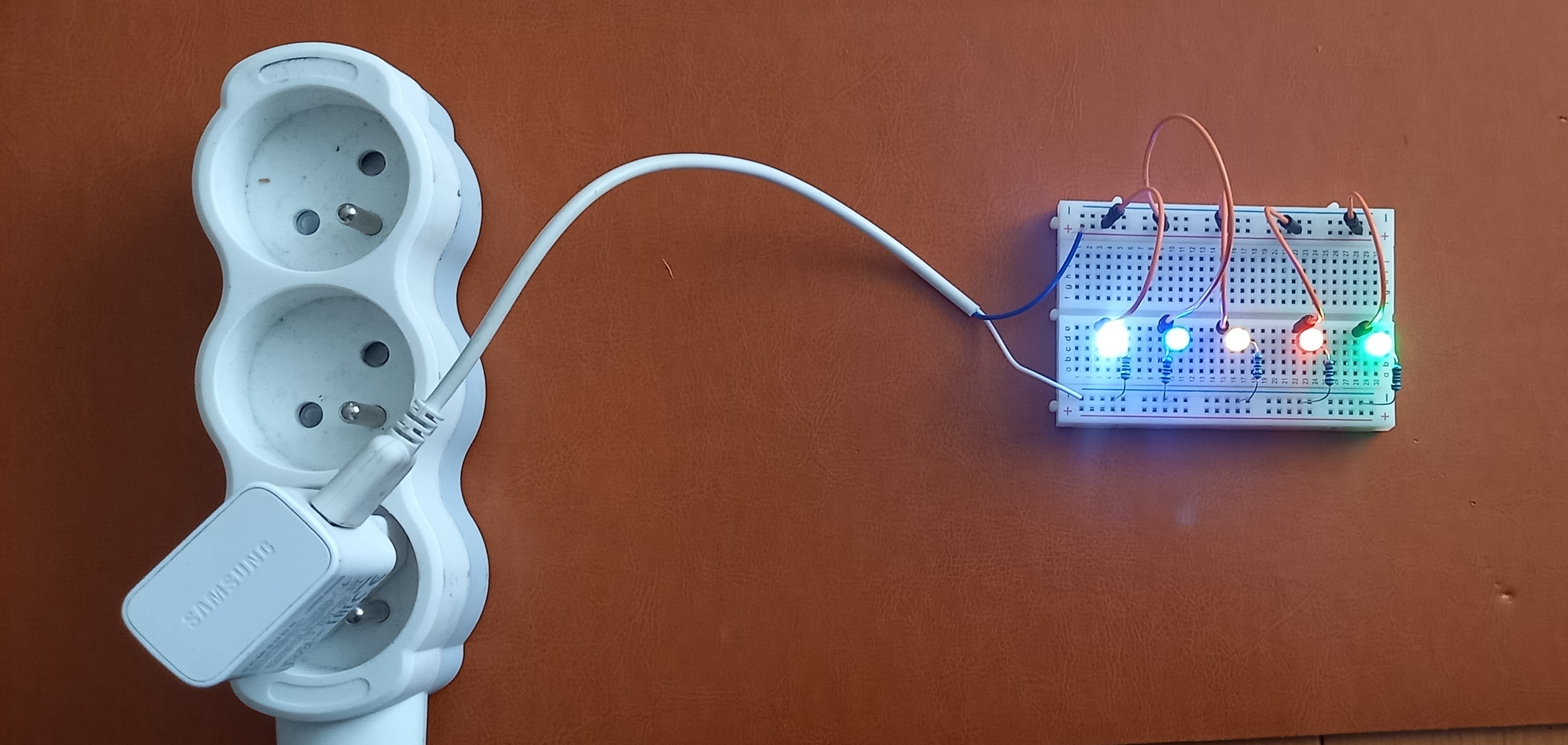
We can connect:
• red
• green
• blue
• yellow
• transparent LED
And create a small LED lighting setup.
The number of LEDs depends on:
• power supply capability
• USB type
• LED current consumption
13. Common Beginner Mistakes
❌ LEDs can be connected any way
✔ LEDs have polarity
❌ A resistor is only needed sometimes
✔ When using USB power, a resistor is mandatory
❌ One resistor can be shared between all LEDs
✔ Each LED should have its own resistor
❌ The brighter the LED shines, the better
✔ Too much current can damage the LED
Conclusion
Now you know:
• what an LED is
• how to determine polarity
• how LEDs differ from light bulbs
• why resistors are needed
• why LEDs can burn out
• how to connect LEDs to batteries and USB
Now try experimenting yourself:
• change resistor values
• use different LED colors
• compare brightness
• connect several LEDs at the same time
In the next lesson, we will learn about diodes and discover how they differ from LEDs.
You can also:
🔧 visit the “Devices” section to see practical applications;
📘 continue learning in the “Education” section;
💬 ask questions or join the discussion on the Forum.