What Is an RC Circuit and How Does It Work?
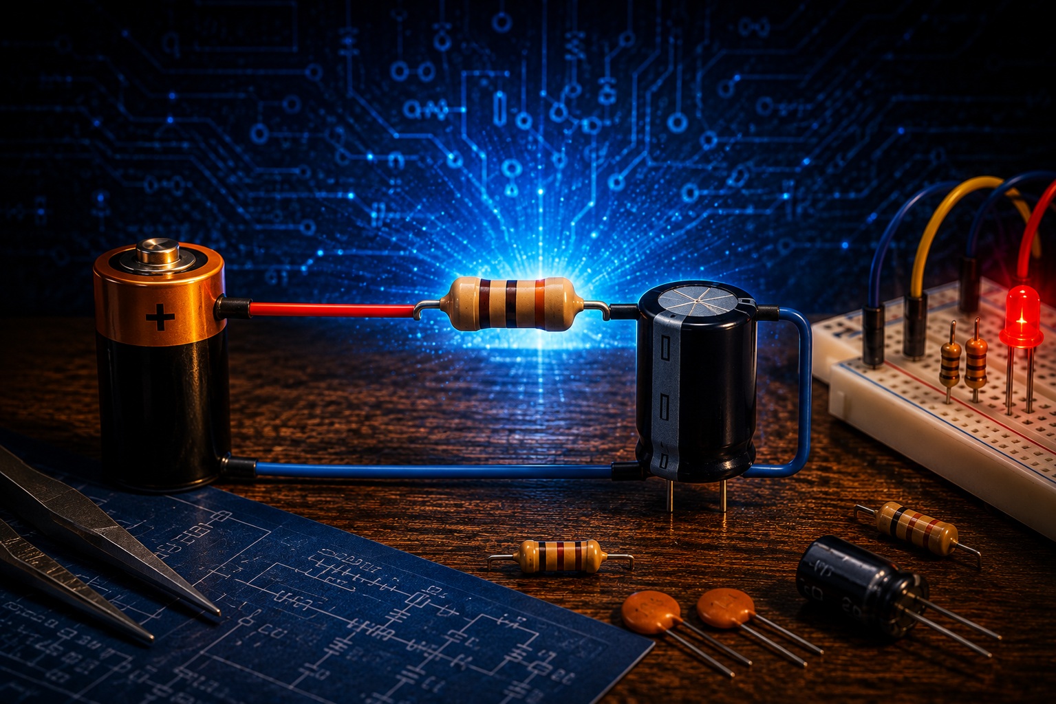
What Is an RC Circuit?
In the previous article, we learned about capacitors and performed a simple experiment in which the LED continued to glow for a short time after the power supply was disconnected.
We discovered that a capacitor can store electrical energy and then gradually release it back into the circuit.
However, this raises another interesting question.
Why did the capacitor discharge gradually instead of instantly?
At first glance, it may seem that everything depends only on the capacitor.
In reality, that is not the case.
The resistor also plays a very important role.
It is the combined operation of the resistor and the capacitor that determines how quickly the circuit charges and discharges.
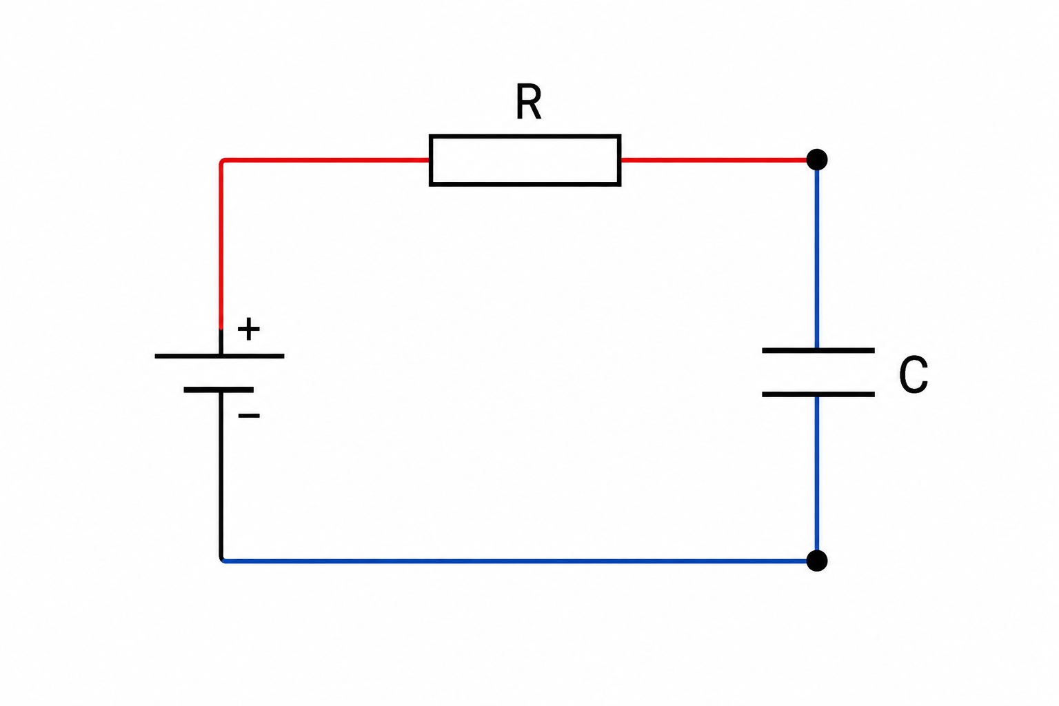
A circuit built from these two components is called an RC circuit.
The name comes from the first letters of the English words:
- R (Resistor) — resistor
- C (Capacitor) — capacitor
Despite its simplicity, the RC circuit is one of the most widely used circuits in electronics. It can be found in power supplies, microcontrollers, measuring instruments, control systems, audio equipment, and many other electronic devices.
Why Didn't the LED Turn Off Immediately?
Let's return to the experiment from the previous article.
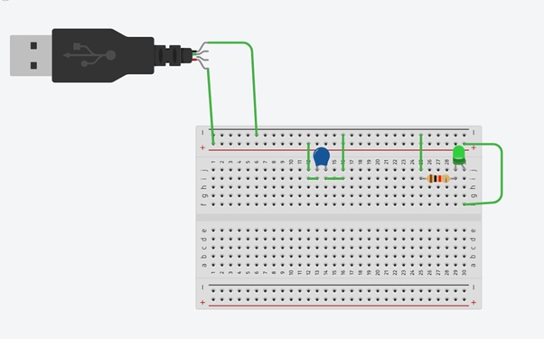
After the power supply was disconnected, the capacitor began to gradually release the electrical energy it had stored back into the circuit.
At the same time, the current flowed through a 10 kΩ resistor, which limited the current.
Because of this, the capacitor could not release all of its energy instantly.
Instead, it discharged gradually, causing the LED to become dimmer and dimmer until it finally turned off.
This simple experiment introduced us to the basic operating principle of an RC circuit.
Can the Charging and Discharging Time Be Calculated in Advance?
In the previous section, we learned that the charging and discharging speed depends on the combined operation of the resistor and the capacitor.
This leads to another question.
Can we determine in advance how long this process will take?
Yes, we can.
To do this, engineers use the concept of the RC time constant.
It allows us to estimate how quickly the voltage across a capacitor will change, even before the circuit is built.
The RC Time Constant
The time constant is represented by the Greek letter τ (tau) and is calculated using a simple formula:
τ = R × C
where:
- τ — time constant (seconds)
- R — resistance (ohms)
- C — capacitance (farads)
At first glance, the formula looks very simple.
However, it forms the basis of most RC circuit calculations.
Using it, we can predict how quickly a capacitor will charge or discharge.
Calculating Our Experiment
Let's return to the experiment from the previous article.
We first used a 100 µF capacitor and then replaced it with 470 µF and 1000 µF capacitors.
In every case, the resistor remained the same:
10 kΩ.
First, let's convert the values into standard units.
- 10 kΩ = 10,000 Ω
- 100 µF = 0.0001 F
- 470 µF = 0.00047 F
- 1000 µF = 0.001 F
Now we can apply the formula:
τ = R × C
The results are:
|
Capacitor |
Time Constant (τ) |
|
100 µF |
1 s |
|
470 µF |
4.7 s |
|
1000 µF |
10 s |
As you can see, increasing the capacitance also increases the RC time constant.
This means that both the charging and discharging processes become slower.
An Important Note
This is where many beginners make the same mistake.
It is easy to assume that if the time constant is 1 second, then the capacitor will be fully charged or fully discharged after exactly one second.
This is not true.
The time constant does not represent the total charging or discharging time.
Instead, it describes how quickly the process takes place.
Therefore, after one time constant has passed, the capacitor is not yet fully charged.
What Does 63% Mean?
When a capacitor charges, its voltage does not increase at a constant rate.
At first, the charging process is very fast.
As more energy is stored, the charging rate gradually slows down.
As a result, after one time constant, the capacitor reaches approximately 63% of its final voltage.
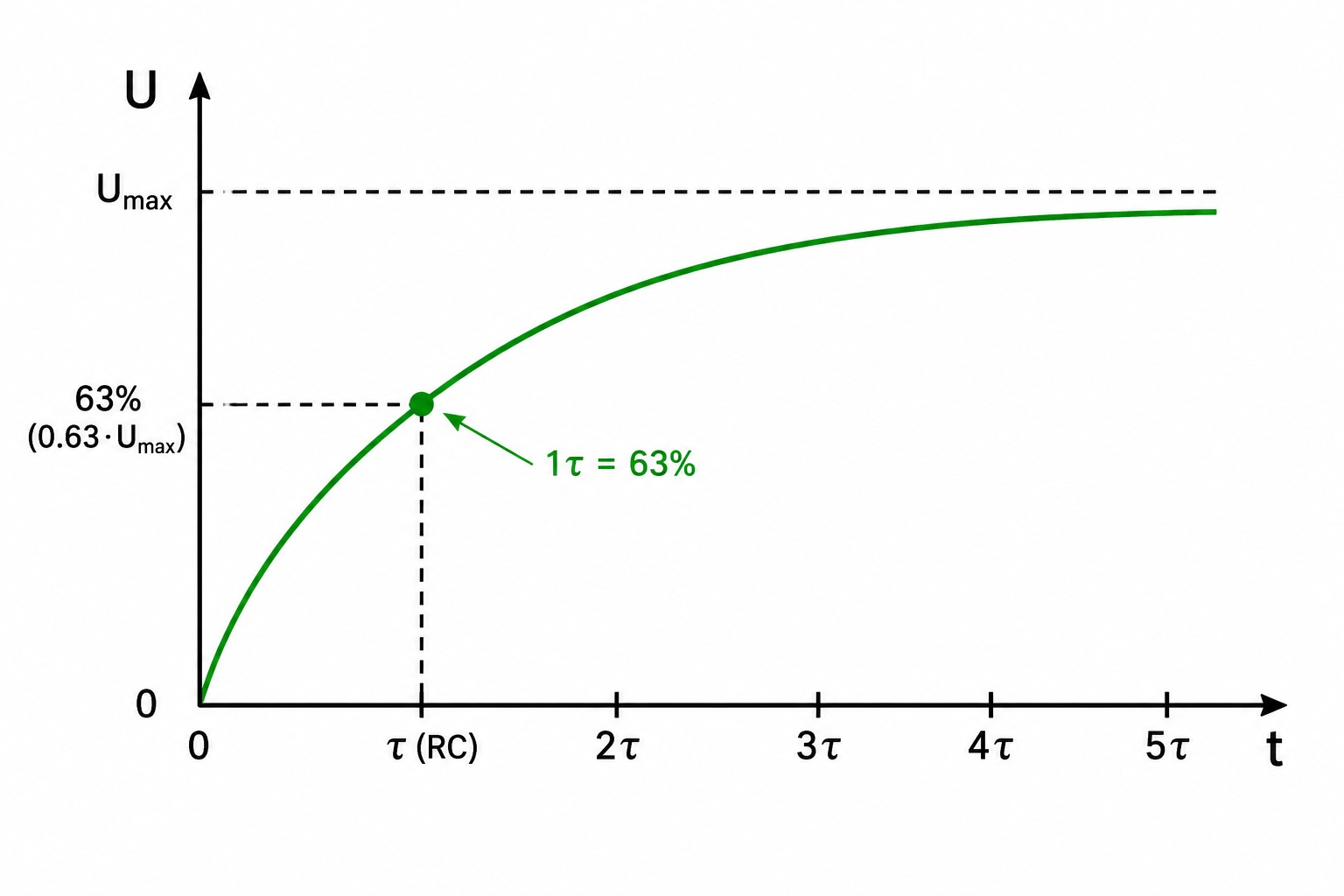
Let's assume the supply voltage is 5 V.
After one time constant, the voltage across the capacitor will be approximately:
5 × 0.63 = 3.15 V
This means that after 1 second, our 100 µF capacitor will be charged to approximately 3.15 V, not the full 5 V.
Charging Continues
The charging process does not stop after one time constant.
The capacitor continues to charge, but more and more slowly.
The process looks like this:
|
Elapsed Time |
Voltage (5 V Supply) |
Charge Level |
|
1τ (1 s) |
≈3.15 V |
63% |
|
2τ (2 s) |
≈4.30 V |
86% |
|
3τ (3 s) |
≈4.75 V |
95% |
|
4τ (4 s) |
≈4.90 V |
98% |
|
5τ (5 s) |
≈4.97 V |
≈99% |
For this reason, engineers generally consider a capacitor to be fully charged for practical purposes after about five time constants (5τ).
From a mathematical point of view, the charging process never truly reaches 100%, but after five time constants the remaining difference is so small that it can be ignored in almost all practical electronic circuits.
What Happens During Discharging?
The same principle applies during discharging as it does during charging.
The only difference is that the voltage across the capacitor gradually decreases instead of increasing.
After one time constant, approximately 37% of the capacitor's original voltage remains.
For example, if the capacitor was initially charged to 5 V, then after one time constant its voltage will be approximately:
5 × 0.37 = 1.85 V
After two time constants, about 14% of the original voltage remains.
After three time constants, about 5% remains.
After five time constants, the voltage becomes so small that, in most electronic circuits, it can be considered equal to zero.
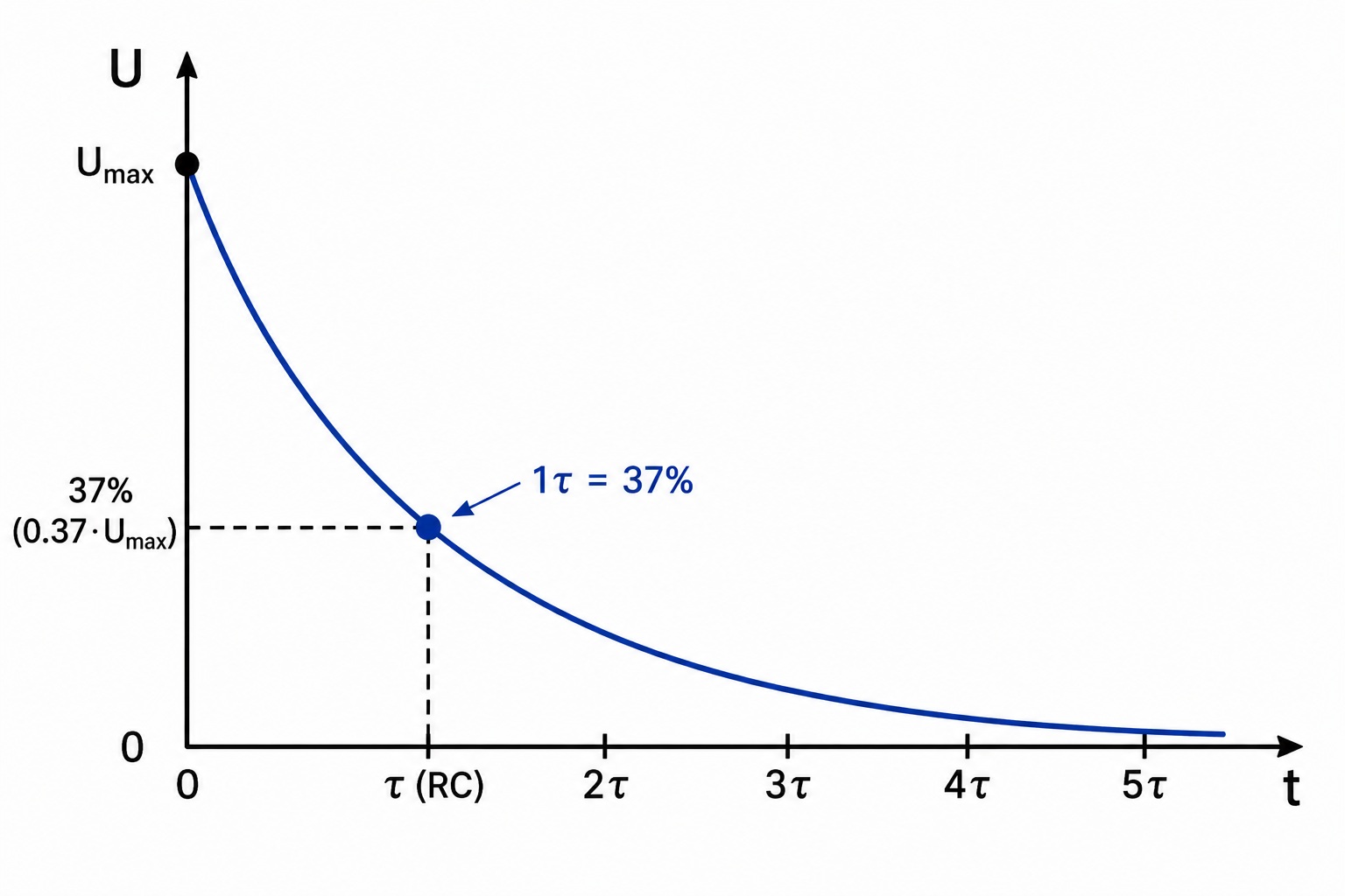
For convenience, engineers often use the following table.
|
Elapsed Time |
Charging |
Discharging |
|
1τ |
63% |
37% |
|
2τ |
86% |
14% |
|
3τ |
95% |
5% |
|
4τ |
98% |
2% |
|
5τ |
≈99% |
≈1% |
You do not need to memorize all of these values.
It is much more important to understand the main principle.
The more time passes, the closer the capacitor voltage gets to its final value.
What Determines the Charging and Discharging Speed?
Now we know how to calculate the RC time constant.
But another question naturally arises.
What happens if we change the resistor value or the capacitor's capacitance?
The answer is straightforward.
Since the time constant is calculated as the product of resistance and capacitance, changing either of these values changes the behavior of the entire RC circuit.
If the resistor value is increased, both charging and discharging become slower.
If the resistance is reduced, both processes become faster.
The same applies to the capacitor.
The larger its capacitance, the more energy it can store, and therefore the longer it takes to charge and discharge.
You already observed this in the previous article when you replaced the 100 µF capacitor with 470 µF and then 1000 µF capacitors. As the capacitance increased, the RC time constant also increased, which caused the LED to remain lit for a longer time after the power was disconnected.
Where Are RC Circuits Used?
At first glance, an RC circuit may seem like a very simple circuit.
In reality, it is one of the most widely used building blocks in modern electronics.
Let's look at some of its most common applications.
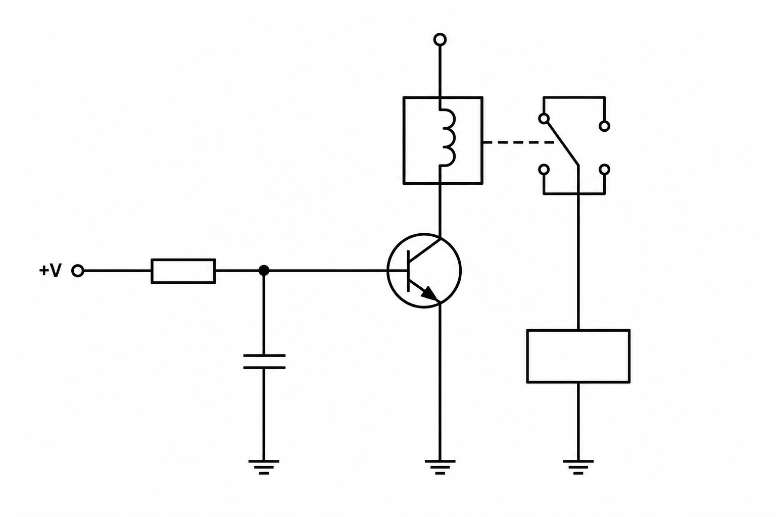
Power-On Delay
In many electronic circuits, not every component should receive power at exactly the same moment.
Some parts of the circuit need a short amount of time for the supply voltage to stabilize.
RC circuits are often used to create this delay.
When power is applied, the capacitor begins charging gradually.
Only after the voltage reaches a certain level does the next stage of the circuit become active.
This principle is commonly used in power supplies, audio amplifiers, and industrial control systems.
Microcontroller Reset Circuits
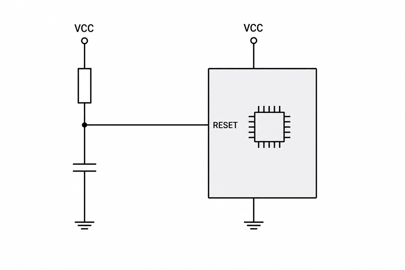
Almost every modern microcontroller includes a Reset input.
When power is first applied, the processor should not start executing code immediately.
Instead, the supply voltage must first become stable.
In many electronic devices, an RC circuit keeps the Reset line active for a short period of time.
Once the capacitor has charged, the microcontroller automatically begins running the program.
This solution is commonly found on Arduino, STM32, ESP32, and many other microcontroller-based systems.
Contact Debouncing
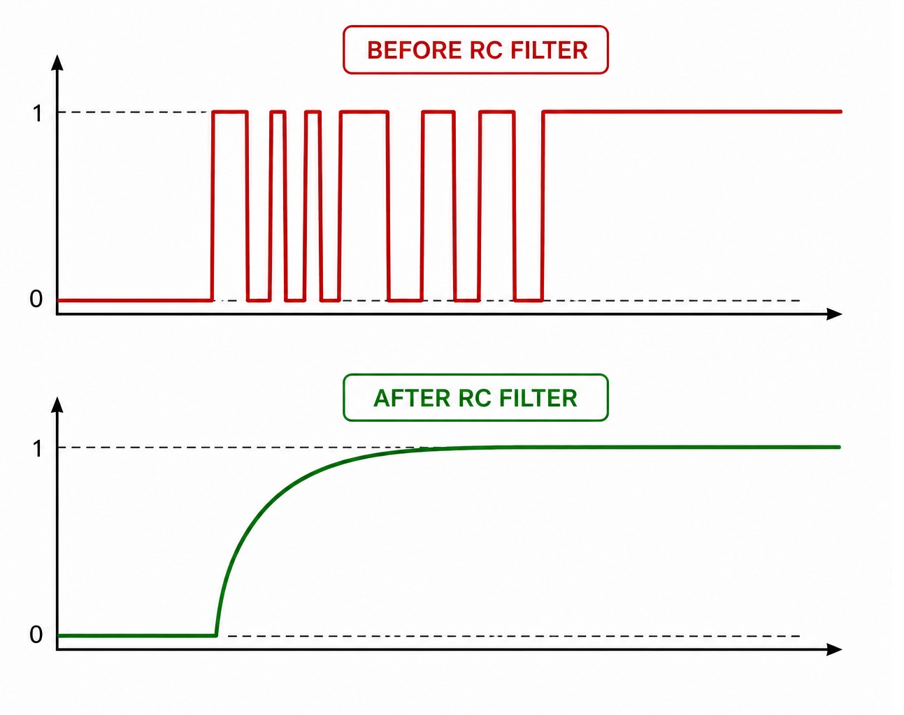
When you press a regular mechanical push button, its contacts do not close perfectly the first time.
Instead, they rapidly make and break contact several times before finally settling.
This happens so quickly that it is completely unnoticeable to a person.
However, an electronic circuit may interpret a single button press as several separate presses.
This effect is known as contact bounce.
An RC circuit smooths out these short pulses, allowing the device to detect a single, clean signal instead of a series of false triggers.
Timing and Delay Circuits
RC circuits are widely used whenever a short time delay is required.
For example, they can be used for:
- delaying the activation of a relay;
- automatically switching a device off after a certain period of time;
- generating short control pulses;
- starting different parts of a circuit in the correct sequence.
In many simple electronic devices, these functions can be implemented using nothing more than an RC circuit.
Signal Conditioning
RC circuits are not only used for timing.
They can also modify electrical signals, reduce the effects of electrical noise, and smooth sudden voltage changes.
This operating principle is used in many types of electronic filters, which we will explore later in this course.
Common Beginner Mistakes
When learning about RC circuits, beginners often make the same mistakes. Understanding these common misconceptions will make it much easier to grasp how RC circuits work.
Mistake #1. Thinking That Everything Depends Only on the Capacitor
After learning about capacitors, it is easy to assume that they alone determine the charging and discharging time.
In reality, this is not true.
A capacitor only stores electrical energy.
The rate at which that energy is stored and released depends on the combined action of the resistor and the capacitor.
That is exactly why this type of circuit is called an RC circuit.
Mistake #2. Misunderstanding the Time Constant
Many people believe that if the time constant has a certain value, the capacitor will be fully charged after exactly that amount of time.
This is incorrect.
After one time constant, the capacitor reaches only about 63% of its final voltage.
In practice, charging or discharging is considered almost complete only after approximately five time constants.
Mistake #3. Ignoring the Rest of the Circuit
In real electronic devices, an RC circuit rarely operates on its own.
It is usually connected to LEDs, transistors, microcontrollers, relays, and many other components.
Each of these can influence the behavior of the circuit.
For this reason, engineers analyze the entire circuit, not just the resistor and the capacitor, when designing electronic systems.
Key Points to Remember
After reading this article, you should remember the following key points:
- An RC circuit consists of a resistor and a capacitor.
- A capacitor stores electrical energy.
- A resistor determines how quickly the capacitor charges and discharges.
- The time constant is calculated using the formula τ = R × C.
- After one time constant, a capacitor charges to approximately 63% of its final voltage.
- During discharging, approximately 37% of the initial voltage remains after one time constant.
- In practice, charging and discharging are considered almost complete after about five time constants.
- RC circuits are used in virtually all modern electronic devices.
Conclusion
In the previous article, we learned about capacitors and observed an interesting effect: after the power supply was disconnected, the LED continued to glow for a short time.
Now we understand why this happened.
It turns out that the discharge speed was determined not only by the capacitor, but also by the resistor through which the current flowed.
It is the combined operation of these two components that forms an RC circuit.
Despite their simplicity, RC circuits are one of the fundamental building blocks of modern electronics.
They are used to create delays, control the startup of electronic circuits, shape electrical signals, reduce noise, and perform many other important functions.
Understanding how RC circuits work will make it much easier to learn more advanced electronic circuits in the following lessons.
What's Next?
So far, we have learned about electronic components that can limit current, store electrical energy, and control how quickly that energy is transferred.
The next important component we will study is the diode.
Unlike resistors and capacitors, a diode has a unique property—it allows electric current to flow in only one direction.
Because of this, diodes are used to protect electronic devices from reverse polarity, convert alternating current (AC) into direct current (DC), and perform many other important tasks.
In the next article, you will learn how a diode is built, why it works the way it does, and where it is used in modern electronics.
You may also like:
🔧 visit the “Devices” section to see practical applications;
📘 continue learning in the “Education” section;
💬 ask questions or join the discussion on the Forum.